I've tried to implement a simple H-bridge to control a motorized pot. Problem is: it works a few times then the transistors die.
It's a textbook implementation, maybe too naive.
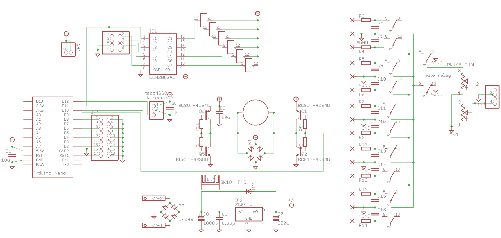
The schematic is below. The bridge is controlled by an arduino, the pot is an ALPS RK168 (100ma when turning, 150ma at the end stop), the transistors are bc807-817, the limiting resistors are 220r.
Should I just switch to stronger transistors (bc337-327 ?) or is there something wrong with the implementation ?
Any particular thing to worry about in the arduino code to care for the transition states ?
It's a textbook implementation, maybe too naive.
The schematic is below. The bridge is controlled by an arduino, the pot is an ALPS RK168 (100ma when turning, 150ma at the end stop), the transistors are bc807-817, the limiting resistors are 220r.
Should I just switch to stronger transistors (bc337-327 ?) or is there something wrong with the implementation ?
Any particular thing to worry about in the arduino code to care for the transition states ?
Not an awful lot that could be wrong there.
1. You might not have enough copper on the transistor legs for adequate cooling.
2. The circuit is self-biasing if the Arduino outputs are ever tristated, merrily conducting between +5V and GND as far as the base resistors will allow, with the expected power dissipation. This will, at the very least, do SOA no good. I'd give both outputs some pull-up or pull-down resistors just in case.
You could try a capacitor across the bases of each half bridge. Maybe one transistor is stuck in storage mode while the other turns on real fast. You could check the emitter current profile first, or just slap a .1u base to base and see if they quit blowing... Assuming it's not easy to control the switching speed of the Nano outputs.
Wait, scratch that. Are you sure you don't want the half bridges running as followers rather than inverting? Even with a 5 volt motor supply, because of your drive/bias scheme you may have a situation when none of the transistors ever shut off, and eventually run away.
Wait, scratch that. Are you sure you don't want the half bridges running as followers rather than inverting? Even with a 5 volt motor supply, because of your drive/bias scheme you may have a situation when none of the transistors ever shut off, and eventually run away.
Last edited:
One issue that I see is that during switching, both of the driver transistors are on at the same time. This is known as 'shoot through' - when both devices are on, then the full power supply voltage is present across the two output devices, and very high currents can flow through the transistors.
The typical thing to do is to use MOSFET devices as well as a bridge driver circuit that is designed to control the conduction overlap of typical devices, and thus prevent shoot through. The bipolars you're using could work in theory, but again, the range of drive voltage where there is overlap is quite large, and it's not clear how much drive the micro controller can provide to fully and quickly turn on and off these devices.
There are a wide range of gate drivers you can use, some of which have built-in switching transistors, and some designed for use with external MOSFETs. One possible device is the On Semi ADP3110A, but there are others. It is designed to work in a buck converter circuit, but that's basically the same thing as a half H-bridge. Check that part out, and others in the same category, and you can get your H bridge to work reliably.
Best of luck!
I think Monte has hit it.
Shoot through, or cross conduction.
You have a common feed to both transistor on each side. That gives you no control over the ON/OFF delays.
I don't think you want/need overlap. What you need is a clean and complete OFF on the conducting transistor, BEFORE the other transistor switches to ON.
I think you should feed 4 signals to your transistor bases and use the software in the Control (arduino) to engineer the delays. There is probably a download that does this, by someone who knows how to H bridge correctly.
Last edited:
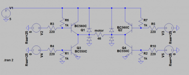
Drive the motor from the emitters of the transistors, not the collectors. That will stop any problem with both transistors being switched on at the same time. Bases connected together from the driver and the emitters together current driving the motor.
Whet is happening at present is when the driver IC relaxes at power on/off, the output voltage can be somewhere in between the rails causing maximum current flow through the transistors Q1 & Q2 and Q6 & Q5, killing the transistors as they are both switched partially on.
No need for four feeds then as the transistors will never be switched on at the same time.
Thx all for the comments. It really helps to get a sense of what's going on ")
The reason pnp and npn are connected this way is to avoid 2 vbe drops. If I swap the transistors, I go from about 4.6V to 3V across the motor. Minimum for proper operation is 4V. A single 5V supply is really something I'd like to keep.
Sadly, it's an all smt affair so switching transistors won't work. I need a new pcb done anyway (because of a dumb error with relay coils polarity...).
Actually, I've got enough free pins to implement 4 control lines. It brings me to the attached schematic. To avoid trouble with high impedance, floating pins state at start-up, I've added pull-up and pull-down to all transistors' bases.
The code will have to look like this: at startup, everything is setup in a all off state (+5V for the pnp, 0V for the npn). Any up or down command reasserts first the off state for all pins, then a short delay (50ms ?) then switches two transistors on, then back to all off. This to avoid ill defined state during reversal of direction. A repeat last command otoh doesn't need to reassert the all off.
Does it seem right ?
And a big thank you again to all.
PS: I really scratched my head to decide where to post this. Is this the right subforum ?
Attachments
...(because of a dumb error with relay coils polarity...).
...
If the relays are DPDT ( or DPST ) and the footprint is symmetrical and if the relays are throughole then you could just mount the relays on the bottom.
That would switch the relay polarity.
been there.
wrt A4988 : qfn package is a pain to solder manually and anyway it doesn't operate on 5V (8v min). I'd rather use a good old l293 in so20 package if I'm going to raise the voltage.
I thought about it actually. Sadly that doesn't work because I've got some smd R and C right next to the pins. And it makes the whole assembly too tall.
Not exactly one's best moment when you realize why the board doesn't work.
If the relays are DPDT ( or DPST ) and the footprint is symmetrical and if the relays are throughole then you could just mount the relays on the bottom.
That would switch the relay polarity.
been there.
I thought about it actually. Sadly that doesn't work because I've got some smd R and C right next to the pins. And it makes the whole assembly too tall.
Not exactly one's best moment when you realize why the board doesn't work.
I think Monte had it. Shoot thru.
I havery some experience of this from my degree assignment.
When making a H bridge using a PIC, the PWM module handily modulates only the High side device logic level output, with the appropriate Low side device switched on.
This greatly reduces the possibility of shoot through damage.
Also I used hexfet devices (irf4905) and a BJT driver stage between the uC and motor.
Some things I learned:
1: uC outputs, usually capable of 25 mA give or take. Unless your motor is puny, you need a driver stage, either for V in the case of FET OPS, or current for a BJT OPS.
2: Use 4 logic control, two line approaches are at best a compromise.
3: be extremely careful with uC startup conditions, initialise logic carefully to avoid shorting the whole bridge at startup.
4: remember any inversions to logic you make using a driver stage.
5: remember freewheeling diodes (and get polarity correct - note to self)
Last edited:
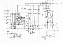
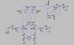
This is how I implemented an H bridge driver for adding full remote control to my amp. You cross couple the bridge so that one side drives the other. I also added a variable supply to bridge so that the motor speed could be trimmed to get the 'correct feel' as it was operated. Logic inputs to the CMOS decoder came from a PIC.
Attachments
I can't believe it's been more than a year I let this project aside. 
Anyway, I finally decided to fix it. So I've built a small h-bridge on perfboard, along the line of the schematic here under. It's based on Mooly's, plus a current limiter set at about 120mA. The transistors used in practice are bc337-327, which are fairly robust, being rated at 800mA.
I also added a small 10ms delay in the code before and after a volume up or down (except when the buttons are continously pushed). I've done my best to kill it (pushing on up or down rapidly) but it seems to resist.
The code is based on the one found in this thread: Simple IR Remote for Motorized Alps Pot directly using Arduino. | HiFiVision.com
If that can help anyone else...
#include <IRremote.h>
int RECV_PIN = 12; // The pin that recieves the IR sensor Output. The leftmost pin when looking at the eye with pins down.
int volDelay = 175; //this value can be changed to move volume for longer increments
long oldValue; // This value will save the last meaningful remote input and reuse it in the case of a repeat
IRrecv irrecv(RECV_PIN); // The core IR parts of the program and the libraries come from Ken Shirriff's blog: A Multi-Protocol Infrared Remote Library for the Arduino
decode_results results;
void MotorOff()
{
digitalWrite(5,LOW);
digitalWrite(6,LOW);
}
void MotorUp()
{
digitalWrite(5,HIGH);
digitalWrite(6,LOW);
}
void MotorDown()
{
digitalWrite(5,LOW);
digitalWrite(6,HIGH);
}
void setup()
{
pinMode(5,OUTPUT);
pinMode(6,OUTPUT); //setting power to motor pins for 5v output
pinMode(11,OUTPUT);
MotorOff();
Serial.begin(9600);
irrecv.enableIRIn(); // Start the receiver
digitalWrite(11, HIGH); // turn off the mute function
}
void loop()
{
if (irrecv.decode(&results))
{
Serial.print(results.bits, DEC);
Serial.print(" --results.value"); //printing newly recieved IR code to serial monitor
Serial.print(results.value, HEX);
irrecv.resume(); // Receive the next IR code. This code is an interrupt, so the arduino can go on with other tasks.
if (results.value==0x77E150EF) //if up button pushed move motor forward with a 250ms shot of 5V
{
oldValue=results.value; //setting the placeholders value
delay(10);
MotorUp();
delay(volDelay); //this value can be changed to move volume in bigger increments
MotorOff();
delay(10);
}
else if (results.value==0x77E130EF) // down button pushed
{
oldValue =results.value;
delay(10);
MotorDown();
delay(volDelay);
MotorOff();
delay(10);
}
else if (results.value==0xFFFFFFFF) // button is held down, do the last thing done, again
{
if (oldValue==0x77E150EF)
{
MotorUp();
delay(volDelay);
MotorOff();
}
else if (oldValue==0x77E130EF)
{
MotorDown();
delay(volDelay);
MotorOff();
}
}
Serial.print(" --oldValue");
Serial.println(oldValue, HEX); // this shows the placeholder at work and starts a new line in the serial monitor
}
}
Attachments
- Status
- This old topic is closed. If you want to reopen this topic, contact a moderator using the "Report Post" button.
- Home
- Source & Line
- Analog Line Level
- H-bridge killing transistors