Only watch not to accidentally short an output while its running or before its discharged by its bleeders for a couple of minutes when turned off. This is not like my shunt regs with a CCS current limit. Its limitless. It blows the fuses and the BC transistors when on and it only blows the BC transistors when off but charged in case of a short, which are dirt cheap parts, but its a narrow space to rework in the sinks gaps.
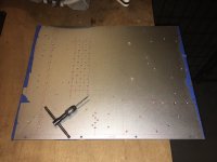
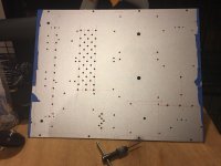
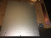
Going to upload images of my second DCG3 unit. These pictures might give you an idea of parts layout. It is MY” layout and some of you might considered different architecture for more optimal space utilization and shorter power and signal passes. This freedom is a beauty of DYI.


Last edited:


Only watch not to accidentally short an output while its running or before its discharged by its bleeders for a couple of minutes when turned off. This is not like my shunt regs with a CCS current limit. Its limitless. It blows the fuses and the BC transistors when on and it only blows the BC transistors when off but charged in case of a short, which are dirt cheap parts, but its a narrow space to rework in the sinks gaps.
Thanks for the tip...I have not yet affixed the heatsinks to the board. Somewhere in the reading, it suggested that. so I power up, measure the outputs for correct voltages, power down, and leave alone to bleed down a couple hours. Sound good?
Russellc
Impressive, alexkosha!
BK
Thank you. The purpose of these images is to give you guy a close look and some ideas of assembly. I will be glad to answer if you have questions and please let me know if you need info about parts that I used. That unit is my second one (for my office use) and that time I desired to go with LDRs volume control. Fist one is running with Goldpoint 48 steps attenuator. It is amazing unit. This one is just finished and have very brief audition. I’ll report about my subjective opinion about its SQ in 2-3 weeks. Personal thanks to Salas for an exceptional support.
Last edited:
Alexkosha, did you engrave it by your CNC? Good looking front panel. Good job.
Yes, it is. I made Front panel in the same exactly way as I did it for my first unit and I used CNC. All the rest of drilling I did manually in my garage.

Attachments
Thanks for the tip...I have not yet affixed the heatsinks to the board. Somewhere in the reading, it suggested that. so I power up, measure the outputs for correct voltages, power down, and leave alone to bleed down a couple hours. Sound good?
Russellc
Yes, good plan. But only a few minutes will do. Just measure that their output voltage has fallen waaaay down before declaring the units empty of charge.
Thank you. The purpose of these images is to give you guy a close look and some ideas of assembly. I will be glad to answer if you have questions and please let me know if you need info about parts that I used. That unit is my second one (for my office use) and that time I desired to go with LDRs volume control. Fist one is running with Goldpoint 48 steps attenuator. It is amazing unit. This one is just finished and have very brief audition. I’ll report about my subjective opinion about its SQ in 2-3 weeks. Personal thanks to Salas for an exceptional support.
Excellent work there Alex. Congratulations. Making a second one means that you really liked the first one over time, happy to know that those preamp builds stand the test of time with many of you guys.
The HD650 uses removable cable with Y split and connection points at the bases of its cups so remove the bridged drive connecting four pin XLR terminated cable from it and use the original cable with the jack connector that came in the manufacturer's box. If you want to keep the special cable for some reason like custom length or its mechanical quality you have to remove the XLR and rewire to a jack. Tip is left channel, ring is right channel, sleeve is the grounds.
I think I will do so....
b) mount a 4-pin female socket in the DCG3 chassis but wire it SE (so pins 1 and 3 to the SE outputs L+R and pins 2 and 4 to signal ground)?
Steef
... and using NC4FD-L-B-1front mount connectors ;-)Thanks,
I myself was planning to use *only* a 4-pin XLR on my chassis and wire it SE
Now I am pondering how on earth to back-mount a 4-pin Neutrik female panel connector to a 10mm thick front panel (considering these things have lock-tabs)...
Steef
- Home
- Source & Line
- Analog Line Level
- Salas DCG3 preamp (line & headphone)