Hi
Have now power on the pre
1 channel do not work right ,,,to high DC on output
it was a fault 9610
i mounted 2 new..and then it looks alrigth
witout the servo ic i have about zerro to 10 millivolt...not bad
with the servo ic zerro to 2 millivolt
also the volt over R10 is 119mv on both channel
now it is time to mount the in and output
Best Bjarne
Can chance on a dead Mosfet or kill one by bad handling (static, floating voltage soldering iron). But the TO-220 insulation to the sink must be carefully done also.
If you are using 10 Ohm R10 then 119mV across that resistor means 119mA bias. A double mono build of such bias is likely to be showing circa 20W on a mains socket consumption meter like the Kill A Watt.
Hi
MY fault ..i meen 119ma --ohms law
the cooling is top ..not even warm,,,
i have it mounted and playing....but only temporary ,,,wiring is bad in the box ..give some noise..
first listening on the sound...it is going to be good
but first,,,totally new wiring and prober grounding...
more to come
a little about what i am playing on
speaker --GR.research LS9 line array
Amp Gryphon Encore
Dac Doedes pcm1794 4decks
playing from Pc over usb
Best Bjarne
True, most people will listen at a 90dB SPL median with 100dB SPL peaks and will describe that as loud enough. The Nighthawks will be at 90dB SPL with just 0.1V and at 100dB SPL with 0.32V when using the strictest sensitivity estimation we could find for them. Maybe Russell will have to include a 2X setting also to evaluate with them during his planned gain tests.
My idea is 2x, 3x, and 4x. When utilizing computer, which certainly is not always, I can use the main volume control on the computer to lower gain. The dragonfly has no objections to having full volume from computer, and using preamp volume, or reducing it via computer. This only seems to be rational, but Audioquest goes to great pains explaining the Dragonflys "internal volume control." I don't quite follow that, but whatever.
Russellc
Those 3.3Κ should be the Rb1 Rb2 bleeders located sideways to each output connector while those 1.2R should be the RxJ and RyJ check point/trim resistors (that may actually show 1R if you zero the DMM first by touching the probes together and you press the DELTA (REL Δ) button). You can alternatively solder them on the back side of the PCB for easy replacement.
My idea is 2x, 3x, and 4x. When utilizing computer, which certainly is not always, I can use the main volume control on the computer to lower gain. The dragonfly has no objections to having full volume from computer, and using preamp volume, or reducing it via computer. This only seems to be rational, but Audioquest goes to great pains explaining the Dragonflys "internal volume control." I don't quite follow that, but whatever.
Russellc
To best estimate various situations gain needs it takes practical tests employing the different gear and replay methods you actually own and use as you say. Tailor made settings is one of DIY's strong points.
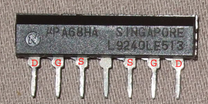
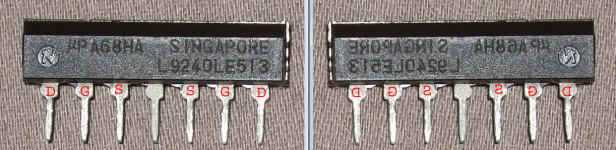
The pins are as marked in this photo. So 1D corresponds as you described.
Looking at its pinout I'm thinking that this part has no right or wrong orientation, right?
Palindrome part..

Is this the right way to do? I see slight increase in distortion from the above schematic.how about using this way for Balanced input SE output.
Looking at its pinout I'm thinking that this part has no right or wrong orientation, right?
Palindrome part..
Its a flipper
Attachments
Is this the right way to do? I see slight increase in distortion from the above schematic.
We have discussed possible ways back then extensively. Including dedicated transformers or special chips. Its a long discussion to repeat. There are several techniques. You should try in practice what input connection modification you find possible for BAL In ---> SE Out when simulating, and evaluate if thoroughly successful given the layout.
Just about done with the pre board, except gain and current choice, and one spot not on BOM, the two resistor pads next to the opamp plug.
Most pics I see here show jumpers. Seems like I read somewhere in the thread they would only need to have resistors populate them if voltages didn't match closely?
Almost done, got the Antek transformers friday, waiting to decide which case from DIYstore.
Should have that ordered shortly.
I select and power supply just need the devices that mount with heatsink installed. I know the 6 devices on the edge of the pre need insulators, mica included with kit. I assume the single regulator on I select and the 4 on the power supply board just need paste?
Russellc
Last edited:
If you mean the RZ/J resistors places, the BOM refers them to paragraph #3 in the guide because its a place you might add some arbitrary extra output resistance or not in the headphones output path. Read #3.
You assumed correctly on the single reg chip of In-Select and on the four TO-220 BJTs of the DCSTB PSUs that they can work with just paste if there is no chance their sinks will be touching grounded metal in a build.
You assumed correctly on the single reg chip of In-Select and on the four TO-220 BJTs of the DCSTB PSUs that they can work with just paste if there is no chance their sinks will be touching grounded metal in a build.
- Home
- Source & Line
- Analog Line Level
- Salas DCG3 preamp (line & headphone)