Just received today a custom O-core power tranformer from China.
But manufacturer misread my specifications and sadly wound one sec. instead of two.
I have only one 18v-0-18v available in a 100w. core.
Before complaints, Salas please lets me know best option here:
-Use as it is, wiring parallel to both channels.
-Order another tr. identical to complete double mono, or
-Order new with two sec. as it should.
Thanks in adv.
You can't share a common secondary set between two PSU's without common voltage issues due to non isolation. Its either you use one transformer and one PSU with its DC output shared between channels (compromise) or you use the double PSUs on double sets of independent secondary AC either wound on a shared core or going full double mono utilizing two separate transformers. Shared core option is just satisfactory, double transformers is costlier but its the most advanced option regarding separation.
") nice to know
nice to knowI am waiting to receive a fairly unknown high end headphone intended for the internal china market.
It has somewhat unusal parameters for a planar magnetic, with a low 34ohm. impedance and 96dB/mW.
I's reported among the easier to drive in the planar magnetic tech.
What bias and gain settings could I set on DCG3 preamp?
It has somewhat unusal parameters for a planar magnetic, with a low 34ohm. impedance and 96dB/mW.
I's reported among the easier to drive in the planar magnetic tech.
What bias and gain settings could I set on DCG3 preamp?
96dB/mW at 34Ω translates to 111dB/V and 30mA RMS. So they are voltage sensitive headphones indeed but they demand some appreciable current.
See in post#1 the last two THD graphs with the Grado SR60 used as load for the DCG3 at 100mA vs 150mA bias. Those cans at 98dB/mW 32Ω have close spec to the ones you are expecting. Their level was realistically loud at 105dB SPL in those measurements. The 150mA bias graph showed a THD benefit. So use that bias.
As for gain setting the standard 3X will be more than enough for your cans with reserve for other less sensitive cans or for some quieter digital recordings or a vinyl source.
dbis, same problem here with the 10mm fronts. This was someone else suggestion. Ideally a drillpress and a one inch cheap or used spade bit that normally would be used for wood.
Drill about half way through from the back side, perhaps a little more, then drill your hole for the selector and/or volume. You can also drill a small index hole to keep the selector switch from accidentally rotating.
You made to use a spade bit larger than one inch.
Drill about half way through from the back side, perhaps a little more, then drill your hole for the selector and/or volume. You can also drill a small index hole to keep the selector switch from accidentally rotating.
You made to use a spade bit larger than one inch.
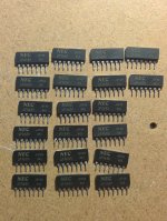
Just started the build and came across a fake/mutated NEC while measuring
the idss of them. Can you find it
FWIW, the idss range from 4.2X to 14.4X mA, all are usable except one.
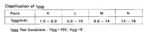
That's a very weird sample. At the bottom right side they also all have the same N43 (fishy). It should mean N class and batch. They must only range between 13mA to 18mA. Else they are fully suspect. My stamped Japan fat variety samples are random, they have different letters K, L, M, and different batch numbers, shiny leads and the NEC stamps are located some at the top left and some at the top middle but all are in faded white color. Their IDSS follows their lettering rank in test.
Attachments
Yup, I suspect that is a bad one that somehow passed QC.
The casing and prints are identical to the rest except one pin too many.
Wonder what it actual is ....
IMHO those are all most possibly forged and the eight pin one is the forger's worst blunder
Yeah, I was very surprised to see the wide range of idss as well. I bought those when this thread firstly started (from ebay, of course), so the demand wasn't even there.That's a very weird sample. At the bottom right side they also all have the same N43 (fishy). It should mean N class and batch. They must only range between 13mA to 18mA. Else they are fully suspect. My stamped Japan fat variety samples are random, they have different letters K, L, M, and different batch numbers, shiny leads and the NEC stamps are located some at the top left and some at the top middle but all are in faded white color. Their IDSS follows their lettering rank in test.
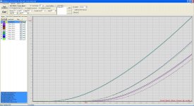
I just checked a few of them with my curve tracer. The "Auto Detect" said N-JFET for both sections with the correct G pin (D, S pins interchangeable). The curves also match the data sheet's (see attachment) VGS vs IDSS curves with closely matched sections, too. Perhaps, they are no worse than those I can buy from ebay these days, sigh.
Attachments
Its a resistor that helps against line output shorting accidents and shapes the phase margin a little better for some inductance and capacitance combinations. It also differentiates the line output from the HP output load, buffering the line out with resistance when phones are also hanging connected. Defines a lab standard 50 Ohm line output. This circuit can be stable alone, as we have repeatedly used it driving various phones harder complex loads even when Rz=zero link, but its also good general practice to have R15 in the line out path.
On the other hand I wouldn't be surprised if someone claimed that having used a Z foil or less/more value have changed something in the sound. Because another value would change the line output damping, and if superior quality is detectable even in same value, yes its in the signal path. The R6 & R7 feedback resistors are significant passive parts too.
Me I have used Dale RN series everywhere and I did not remove R15 ever so I can't guarantee it will work better or as safe without it across a range of loads or describe any subjective impression for changes there.
Just what i like to know Salas
i do not know if it the same thing with this resistor ..as some use to lower output from
a cd player to a amp
it can be heard..sometimes with good result,,but some will say that the sound get smooths ..and lost dynamik
if it not destroy the preamp ,,it will be worth trying
i do not know if it the same thing with this resistor ..as some use to lower output from
a cd player to a amp
it can be heard..sometimes with good result,,but some will say that the sound get smooths ..and lost dynamik
if it not destroy the preamp ,,it will be worth trying
- Home
- Source & Line
- Analog Line Level
- Salas DCG3 preamp (line & headphone)