Sharing same secondaries between two bridges... Does the trafo or bridge diodes get any hot? Or is there some hum?
The trafo gets aprox as warm as the heatsink,but its a rather small trafo too
I will connect it to my headphones and listen for hum.
You probably used this big heatsink because it was available, right ?
And there comes the question for those living in hot-climate countries (like Greece)
use big (maybe oversized) heatsink or give more ventilation to the chassis ?
Don't tell me to experiment, I have dozen projects, none closed, it's a course I tell ya
And there comes the question for those living in hot-climate countries (like Greece)
use big (maybe oversized) heatsink or give more ventilation to the chassis ?
Don't tell me to experiment, I have dozen projects, none closed, it's a course I tell ya
Solid case looks cool not to mention that custom-made holes (laser/plasma cut) cost. But I'm worried about heat in summertime. One solution is to have the heatsink not enclosed even if put in the bottom of the chassis. Seen it in amps too, a whole part of the bottom cover cut in the dimensions of the heatsink.
The problem is not only the preamp module but also the psu. Even though DCSTB was colder than BIB/UBIBs the center heatsinks where quite hot.
The problem is not only the preamp module but also the psu. Even though DCSTB was colder than BIB/UBIBs the center heatsinks where quite hot.
Hi Salas
I am new to building a DCG3 and have assembled the DCSTB power supply and it all works fine and I get 17.14 from both channels and all the LED arrays light up evenly
However I have a question related to R1 & R2 I fitted the 33R as per the bom but on the packet that contained the PF5102 it is written use 1r for R1 & R2?, should I change these resistors?
Unusually for me ? I forgot to write down the IDSS for the JFets but I have 4 sticker's and the state 4.74, 4.8, 5.25, 5.19
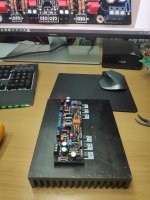
There will be 2 x 18-0-18V transformers and M1,2,3 transistors will be bolted to the right heat sink
 IMG_2952 by Alan Towell, on Flickr
Alan
I am new to building a DCG3 and have assembled the DCSTB power supply and it all works fine and I get 17.14 from both channels and all the LED arrays light up evenly
However I have a question related to R1 & R2 I fitted the 33R as per the bom but on the packet that contained the PF5102 it is written use 1r for R1 & R2?, should I change these resistors?
Unusually for me ? I forgot to write down the IDSS for the JFets but I have 4 sticker's and the state 4.74, 4.8, 5.25, 5.19
There will be 2 x 18-0-18V transformers and M1,2,3 transistors will be bolted to the right heat sink
IMG_2952 by Alan Towell, on FlickrAlan
Such notes should be related to special selections. I don't know for sure but probably R1,R2 1R are recommended because the particular PFs are already around 5mA Idss which is the target so the 1R are used to simply make the circuit. The 33R are recommended to surely bring down Idss by degeneration in random higher Idss samples.
Since you already get 17.14V from both psu channels all seems well evened out somehow so my advise would be don't rework anything because result is fine. Nice box by the way.
Since you already get 17.14V from both psu channels all seems well evened out somehow so my advise would be don't rework anything because result is fine. Nice box by the way.
Use the 1r on those jfets. 33R was for 6-8ma IDSS, but the yeild was too low at that value.
Oops I was thinking about it while you had answered it.
Yeah its a nice solid case meant for an integrated amp but should work great for this pre ampNice box by the way
I bought it from ebay a couple of years ago
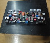
 IMG_2968 by Alan Towell, on Flickr
 IMG_2969 by Alan Towell, on Flickr
Alan
I have finished the DCG3 board apart from R3 150R as there wasn't any in the kit, there is 2 x 220R, is this a mod or a mistake
Has there been any other mods from the standard BOM or diag
 20200524_194951 by Alan Towell, on Flickr
Alan
Has there been any other mods from the standard BOM or diag
20200524_194951 by Alan Towell, on FlickrAlan
Its I have given instructions to mind the mA result of the JFET + resistor not the resistor value per se. So if a batch of J3s is of higher IDSS the R3 is matched for mA result. Its linked from post#1 anyway but here is it again: About J3/R3
- Home
- Source & Line
- Analog Line Level
- Salas DCG3 preamp (line & headphone)