Problem even sillier than I thought. Checking all my transistors not yet installed I have the two M3 DN2540 pieces, But no IRF9610! I have two Q3 MJE15030G, and I have two Q1 MJE15031G.
This means I put all 4 IRF9610 devices on the power supply board in the heat sinked positions. Why the + positions voltages are correct, I do not know! Is this even possible?
Now to remove all 4, (assuming the are all IRF9610) and replace with proper Q1 and Q3 transistors. If the two positive transistors are correct, then there must have been a mixup when the parts were being put into kits. I think the smart money is on me installing all four of the IRF 9610s on the power supply board in the place where Q3 and Q1 should have been.
Is it even possible the IRF9610 would work in the - section of the power supply? (In the Q1 position?)
Russellc
I don't have time to look in detail how it became possible because I am off to meet a friend right now, but the positive side asks for the PNP MJE pass transistor so maybe that is why the PMOS (9610) could basically have worked is my fast guess. The MJE and the IRF are pin order compatible for base to gate analogy etc. We had Mosfet or BJT output choice in the SSLV1.1 reg either with IRF or MJE for instance. The negative side asks for the NPN MJE so no chance for a PMOS to successfully sub that.
Thanks, I just got the heatsinks off, and yes they are all four the IRF9610 transistors.
Holly mixed up bags of parts!
Now, before I remove them, were the IRF9610 transistors all matched? and if so, in pairs or all four? Not sure in what order I misinstalled them but if all four parts are matched, shouldnt make any difference, if in pairs I will need to measure them to "rematch" them in proper pairs. May need to ask Teabag about that.
Solder iron heating up....
Russellc
Sounds good, teas's boards are heavy duty thick, I have wicked up solder but they are still tight, a couple budge if center pin heated, then one side or other and a little pressure applied side ways.
If this doesn't work, may try puddle method, but dont know how that will work on these thick boards. May have to clip them off, then wont reach heatsink hole properly.
Russellc
If this doesn't work, may try puddle method, but dont know how that will work on these thick boards. May have to clip them off, then wont reach heatsink hole properly.
Russellc
Ask Tea for that, but I don't think there should be any selected M1 Μ2 (9610). M3 (DN2540) should be the selected ones for predicted bias.
The IRF9610 are not matched, just ordinary. The M3 are matched.
Sounds good, teas's boards are heavy duty thick, I have wicked up solder but they are still tight, a couple budge if center pin heated, then one side or other and a little pressure applied side ways.
Russellc
Any body tried puddle method on these thick boards? Any desolder trick's appreciated! No desoldering station unfortunately.
Russellc
If it were me, I would clip them all out, and then desolder and or yank one FET leg out at a time. Then replace them all. I can send you more fets if you need. My son can desolder a TO-220 on one yank with a holding the thick part of the iron across it, but has not tried tried it with this board. More for practice in his own right for school.
Kind of late but this is what I use and works very well.
45-Watt Desoldering Iron with Vacuum Bulb
nash
45-Watt Desoldering Iron with Vacuum Bulb
nash
Kind of late but this is what I use and works very well.
45-Watt Desoldering Iron with Vacuum Bulb
nash
I've got one of those, didnt have much luck with Tea's extra thick boards.
Russellc
MJE transistors are restored on the DCSTB's sinks you meant, right?
Your reported output voltages are excellent now. Nothing more to do there.
Cool. Yes, the MJE transistors I will wait for new IRF9610 set to arrive from Teabag, need the heatsink and we can button this one up....hopefully.
May have a wiring question or two about selector switch and I select board.
Russellc
Last edited:
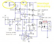
To do different stages rails you would need to hack the board with a hobby knife. Watch J3's max VDS though.
Got my four R-core transfomers and got the quasimodo board finished as well. Waiting for the UBiB and am preparing the HP board meanwhile.
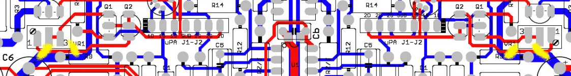
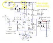
Already did cut the GND for full dual mono ( Salas DCG3 preamp (line & headphone) ) but to find the right spot to cut traces of the current mirror is next to impossible, given the black coating of the board.
Could you please check my close up picture of the layout, where to best cut the traces for both cannels (yellow marks) ?
I possibly didn't quite get it, is it indeed at R9 where +V is supplied by a via ?
Attachments
Last edited:
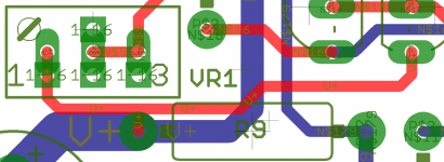
It was easier to break up the positive rail of the stages by breaking the R9 via with kinda funnel, than to cut traces.
")
Always easy to go back at any time by simple bridging, just in case severe problems may arise.
Always easy to go back at any time by simple bridging, just in case severe problems may arise.
Attachments
Last edited:
Good point.
I'm just laying out the rails and the turnouts right now, because for me its way easier to do those preparations before populating the board.
I guess I will start out with the stock scheme, than proceed towards a simple R/C decoupling (down to 150 ohm / 100uF / 10Hz possibly), than towards a split PS at same voltage and finally towards a split voltage at double + voltage for the first stage.
Should be a nice learning curve, I guess, given the very revealing 4-wire modified AKG K712 I'm really fallen in love with.
Most probably there will be a different approach towards my ideas of a dual mono quasi star point mass as well.
Last edited:
- Home
- Source & Line
- Analog Line Level
- Salas DCG3 preamp (line & headphone)