Hi there from a fairly unskilled (electronics wise) muso needing some help getting a few circuits right for a new project.
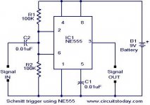
My project involves numerous triggers driven from my guitar, various drums and other instruments using simple piezo transducers as the pickups. From the trigger instruments the signals do various things such as acting as key inputs for gates and driving voltage controlled synth arppegiators and things the like that via a Schmitt Trigger circuit using a 555 IC. (see that circuit below).
What I need is a simple pre-amp circuit (with a variable output) so I can get the right level for each trigger signal's assigned task. Each instrument supplying the trigger has different output levels, and drummers hit with different velocities for example, so I'd like something easy to make that can run just behind the trigger and be adjusted to provide just the right level for the schmitt trigger or other application that I'm sending the trigger to. If I use a little mixer to test how much gain I need it seems to be a range of about up to +60 db. I'd also like to be able to turn it down to zero signal or attenuate the output downwards if necessary.
A secondary requirement if it's easy enough would be a pot that can shape the trigger input envelope such that I can adjust the threshold for signal cut off. That way if the trigger is coming from a hi-hat for example, I can make it a steep cut off envelope which would allow the drummer to open the high hat and let it ring while still only supplying the trigger with the initial hit. Also some of the triggers controlling various gates will be driven by vocals so I might want to extend the envelope to enable a longer gate open threshold.
So sound quality as per guitar signals isn't really an issue - just looking for clarity of signal-on and signal-off, ideally with the input amplitude envelope control plus variable output described above.
So I'm hoping there's a good simple and cheap circuit someone can suggest for me - I'm going to need to build a fair few of them for this project so a simple quick build and cheap cost is also a must!
Many thanks in advance!!
Attachments
Yep - just one pulse at the 555 output per trigger input spike is all I need. I have it working already as per the circuit I posted, but I have to hit the piezo trigger too hard to get the output pulse. If I go through my little Mackie mixer on the way in and boost the signal about 30-40db it has the right "action" in terms of trigger dynamics - so I'm looking for a simple circuit to do the same thing (including a variable output so I can set the output level exactly for various trigger strengths at input).
The bonus feature if it's easy would be that I could adjust the envelope of the trigger input that is fed through the system so I can gain a single trigger from a "transient plus ringing signal" input such as an open hi-hat. In that case all I want is the transient to go over the threshold so I'd like to be able to "shape the way the input is driving the 555 circuit. Maybe variable ouput is enough to achieve that?
What I didn't add is that for the particular application that is using vocals as the trigger I would be going directly to a gate key input and not the 555 circuit. The gate itself has threshold, attack and release settings so maybe having that second feature is not necessary. If the signal is strong enough at the output from the vox input I can just set the release on the gate to hold open for longer and that would achieve the desired effect.
However, for the Piezo signal input I would love to have the amplitude envelope component included so I can get a spike from the initial transient and nothing as the hi hat continues to ring. Then the next time it's hit I'd get another spike.
So in thinking about it more - (always worth thinking more before posting as it turns out!) the main request is for 1. A mic level input circut outputting -infinity to +60db gain, and 2. a high impedence (Piezo transducer signal) input circuit outputting -infinity to +60 output, WITH an input amplitude envelope adjustment if possible! Hope that makes sense!
I'd use an op amp for variable gain. Fixed stable gain, no temperature effects of set point. 4558 are cheap and univerally available. If you capacitor couple the input signal and bias the op amp input with a couple of resistors somewhere in the middle of the supply, you don't need the traditional +-15 v supply. I'm using an 18 v race car wall transformer for my mixer. A pot to turn down the input, Rf about 10 x Ri for a gain of about 10, what's not to like.
I think 555 are a bit obsolete now we have fets. I'm using 2n7000 nfets as timing components, trigger about 5 v on the gate. If you have plenty of drive current for the gate, (like from an op amp output) salvage nfets from blown up switcher supplies would work, too. I find those things on the curb all the time - about 100 fets in a blown 50" LED TV two weeks ago. Delay happens when gate goes low and capacitor charges up. If you need and edge trigger, capacitor couple the gate to the source. Bad fets, if you short gate & drain, the source is usually 0 ohms to the drain too. Good ones, infinity ohms.
I think 555 are a bit obsolete now we have fets. I'm using 2n7000 nfets as timing components, trigger about 5 v on the gate. If you have plenty of drive current for the gate, (like from an op amp output) salvage nfets from blown up switcher supplies would work, too. I find those things on the curb all the time - about 100 fets in a blown 50" LED TV two weeks ago. Delay happens when gate goes low and capacitor charges up. If you need and edge trigger, capacitor couple the gate to the source. Bad fets, if you short gate & drain, the source is usually 0 ohms to the drain too. Good ones, infinity ohms.
Last edited:
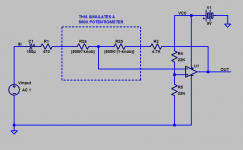
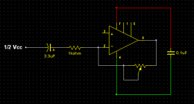
Here's a PreAmp circuit that should work for both audio inputs. The only difference is the value of the Potentiometers, & the input Resistors/Capacitors.
For the Mic PreAmp Ra = 10k Ohm. For the Piezo PreAmp Ra = 1M Ohm
For the Mic PreAmp Ca = 0.22uf. For the Piezo PreAmp Ca = 0.0022uf
For the Mic PreAmp the Potentiometer = 47k Ohm. For the Piezo PreAmp the Potentiometer = 1M Ohm
The Potentiometers give a variation between zero gain & full gain. The values, along with the 1k resistor, should give enough level to trigger the 555.
I suggest a 12V Power supply to feed both circuits.
You might like try experimenting with the 555 to increase the pulse length output time. In the meantime, try the PreAmp circuits.
Attachments
Thanks for all the suggestions everyone - Zero D, is that op amp in the circuit a 4558 as suggested by indianajo? I like the look of your circuit as it's simple and I should be able to build a few of them fairly easily. Question though - I'm running the 555 circuit on a 9v battery, and can get it to fire with even with only a direct signal from striking the piezo fairly hard. So I don't think I require a huge voltage output from the pre-amp, just more than I've got at the moment. Also since the 555 input trigger needs to be a certain threshold below the power supply itself for the 555 to fire, could I use a 4.5v power supply on the preamp circuit you supplied and still achieve the desired result? I want to avoid bulky powersupplies and extra power leads for now if possible.
The OpAmp/s ideally should be a FET type for high impedance inputs such as Piezo's, eg TL071/72/74 range, which are inexpensive. But the ones for the Mic's could be for eg, 5532 type which are also inexpensive. The 4558 doesn't have enough gain/bandwith for the up to 60db gain you requested ! Whichever ones you use, make Sure they are "Unity gain stable" The above i suggested are. Don't forget to apply the usual 0.1uf Caps across the Opamp supply pins. A correction on the pot values, they are the other way round, i mistyped ! For the Mic PreAmp the Potentiometer = 1M Ohm. For the Piezo PreAmp the Potentiometer = 47k Ohm
If you can trigger the 555 directly from the Piezo, then it's putting out more voltage than i estimated ! In which case you could make that Pot = 4.7k Ohm
I wouldn't recommend less than a 9V DC supply. The one PS could supply ALL the 555's & OpAmps. I showed the supply connected like that ! Also, you would Only need one set of components for the Mid point supply = 1/2 Vcc to feed All the OpAmps.
Great - thanks for that followup Zero D - I'll go with that, and can see how I can put the preamp and the 555 circuit in the same unit sharing the one PS, which is certainly ideal. I'll make the input a switching one to cut power when it's not plugged in and all should be sweet. I'll patch it all up next week on a breadboard to check out how the two circuits operate together, and will follow up with a post here once I've tried it out. Thanks for the circuit and advice!
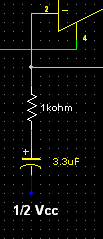
Sorry - can you clarify Zero D? Have you changed the 220uF cap to a 3.3uF cap? And is pin 4 still going direct to ground? I guess that's what the green line means, but if you didn't mind updating the complete original circuit you posted it would be clearer for me. Sorry - just a bit underschooled in the engineering side of all this - so it helps if it's a bit "colour by numbers" for me! Thanks ")
Have you changed the 220uF cap to a 3.3uF cap?
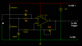
No, it's a different cap in Series with the 1k resistor, which will do what i explained. It also helps to filter out unwanted low frequency signals which could falsely trigger the 555.
And is pin 4 still going direct to ground? I guess that's what the green line means
Yes.
0.1uf Caps across the Opamp supply pins
See my screenie to show you how to connect the above components. Place/solder the 0.1uf caps leads as close as possible between Pins 7 & 4 on the circuit board tracks. I don't have time to draw/sim the whole circuit again, but it's Exactly the same as before, apart from the additions as shown today.
Attachments
Update on 555 trigger pre-amp
Hey there again - Zero D and anyone else following - have tried the circuit suggested and it's getting exciting! The triggering is definitely improved which is opening up all sorts of musical possibilities....
However... I still need more gain. Zero D, by checking on my mixer it looks like I'm getting a little more than 10db gain from the pre-amp circuit and I could really use at least double that... I'm using the TL071 OpAmp as suggested, which was readily available... Have also bybassed the pot to ensure I've not lost anything there (just bridged pins 2 & 6) - so I believe it's working at max output.
In comparison, if I input my piezo output into my Mackie instead and boost it +20db or more I get the gain I need to trigger the 555 as required - just not quite enough yet from the pre-amp circuit stand alone. Almost enough, but not quite...
Can I boost that signal further by changing any of the components? Is there a more powerful OpAmp that could do the trick?
Any further suggestions would be much appreciated!
If you are using the schematic in post #6, remember that its minimum gain is +1.0 ("0 dB"). It does not attenuate.how much gain I need it seems to be a range of about up to +60 db. I'd also like to be able to turn it down to zero signal or attenuate the output downwards if necessary.
Last edited:
Great! That really helped! I've now been fooling with a range of values across that bridge between pins 2 and 6 and it's provided me with the adjustment I need for the range of responses I'm looking for! Turns out a 5K pot in series with a 200 Ohm resistor seems to do the trick. For some playing situations I want fewer triggers fired - say just those on my louder dynamics, and other situations I want it to catch almost every note. The adjustment provided with the 5k pot and 200 Ohm resistor seems to provide that range. Great news!
Thanks heaps for your help Zero D (and Mark, Indianajo). It's great to have been able to sign up to this forum and get the info I needed. Learned a lot too! Will stay in touch and let you know more as the project develops..
I've now been fooling with a range of values across that bridge between pins 2 and 6 and it's provided me with the adjustment I need for the range of responses I'm looking for! Turns out a 5K pot in series with a 200 Ohm resistor seems to do the trick. For some playing situations I want fewer triggers fired - say just those on my louder dynamics, and other situations I want it to catch almost every note. The adjustment provided with the 5k pot and 200 Ohm resistor seems to provide that range. Great news!Thanks heaps for your help Zero D (and Mark, Indianajo). It's great to have been able to sign up to this forum and get the info I needed. Learned a lot too! Will stay in touch and let you know more as the project develops..
Last edited:
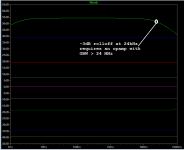
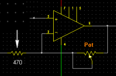
For some reason in Post # 17 a screenie i did didn't get uploaded for That Res I've included this for reference.
For the Piezo circuit.
With a pot of 47k & Res of 470R = 101 times max gain.
With a pot of 47k & Res of 1k = 48 times max gain.
With a pot of 4.7k & Res of 470R = 10.1 times max gain.
With a pot of 5k & Res of 200R = 26 times max gain.
With what you said you have recently done, you have LESS gain than either of the first two above options suggested to you earlier ! So either of the first two above options should have been more than enough to reliably trigger the next stage. Plus as you could vary the pot from full gain to zero gain, you should have been able to find the sweet spot you required. Why you wern't able to ?
By the way in Any of the above, the Pot & Res are NOT in series. The Res & Cap to 1/2 Vcc are in series. Do NOT forget the 3.3uf series Cap ! 4.7uf would be ok too instead.
Attachments
Ah, I see what you mean - Thinking you meant the Pot res value I fooled around with adding resistors along with the pot between pins 2 & 6. I left the 1k res in line with the cap to 1/2 Vcc alone. Everything else was as suggested. Not sure if what I did makes any sense but I was looking to have maximum effect in terms of wide adjustments on the pot, and adding resistors seemed to help. If I'm gaining a 26 X of gain increase that would be plenty, as too high a gain causes unwanted triggering. Right now the lowest setting on the pot has reduced triggering and the highest just that bit too much so that's working for me at the moment. I'm away from the studio for a few days but when I get back there I'll try it as you described in Post 19 and see what difference it makes.
As far as why I couldn't get it happening with the Pot the first time round, I'm not sure. Maybe I had misplaced a connection and didn't realise.
At least I have it responding pretty well at the moment! Thanks again for you help.
As far as why I couldn't get it happening with the Pot the first time round, I'm not sure. Maybe I had misplaced a connection and didn't realise.
At least I have it responding pretty well at the moment! Thanks again for you help.
Last edited:
- Status
- This old topic is closed. If you want to reopen this topic, contact a moderator using the "Report Post" button.
- Home
- Source & Line
- Analog Line Level
- Need finding simple high impedance pre-amp to boost signal to Schmitt Trigger circuit