I'm using a PGA2320 stereo volume control IC to attenuate a single channel. Directly before and after the volume control are op amp buffers (non-inverting, unity gain).
Would routing the same signal into both channels and then averaging the result at the output buffer help to improve performance in any way (e.g., lower noise)? Or does paralleling the resistor ladders provide no benefits compared to simply leaving one channel not connected?
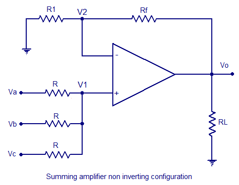
As the output buffer is already in place it would hardly take any extra components or PCB space to do something like this:

Using a balanced connection would be a better idea. While they don't specify this in the data sheet, most of these multiplying DAC type attenuators work better when used in a balanced connection because some of the static errors of the switches and ladders will cancel when used differentially.
I'm a big fan of balanced circuitry anyway, but take a look at the specs for this attenuator chip MAS6116 – Stereo Digital Volume Control IC | Micro Analog Systems They specify improved performance in a balanced configuration, and the same thing will apply to the PGA2320.
I'm a big fan of balanced circuitry anyway, but take a look at the specs for this attenuator chip MAS6116 – Stereo Digital Volume Control IC | Micro Analog Systems They specify improved performance in a balanced configuration, and the same thing will apply to the PGA2320.
I'm using a PGA2320 stereo volume control IC to attenuate a single channel. Directly before and after the volume control are op amp buffers (non-inverting, unity gain).
Would routing the same signal into both channels and then averaging the result at the output buffer help to improve performance in any way (e.g., lower noise)? Or does paralleling the resistor ladders provide no benefits compared to simply leaving one channel not connected?
As the output buffer is already in place it would hardly take any extra components or PCB space to do something like this:

If you keep the impedances low (Johnson noise), the 2 channels in parallel will actually have a higher signal-to-noise RATIO. The noise will add as RMS but the signals (in phase) will add linearly. The noise will go up by the square root of 2 (number of channels) but the signal will go up by 2. This 'trick' was done in commercial units back in the '70s. Ampex used 4 amplifiers in parallel to improve S/N in the AVR-3 quadruplex VTR.
G²
Using a balanced connection would be a better idea. While they don't specify this in the data sheet, most of these multiplying DAC type attenuators work better when used in a balanced connection because some of the static errors of the switches and ladders will cancel when used differentially.
I'm a big fan of balanced circuitry anyway, but take a look at the specs for this attenuator chip MAS6116 – Stereo Digital Volume Control IC | Micro Analog Systems They specify improved performance in a balanced configuration, and the same thing will apply to the PGA2320.
Thanks for the tip! The MAS6116 looks like a rather fine IC for balanced volume control. Interestingly, the TI datasheet doesn't specify the configuration that was used to obtain the AC characteristics in the PGA2320 datasheet, so I'm assuming 🙂rolleyes🙂 that they reflect my type of usage scenario here.
I had already come across Bonsai's impressive 'SCA-1' preamplifier that uses the PGA2320 in such a configuration. The thing is, though, all my inputs are single-ended. Additionally, the input DAC board and outputs (a headphone amplifier and a speaker amp) are in the same chassis, so the usual benefits of going balanced with respect to rejecting noise from long cable runs and minimizing ground loops relate to issues that can be largely avoided here. (Or at least that's what I'm hoping. 😉)
Last edited:
Thanks for the explanation. I'm gonna put some jumpers on the PCB to try the different configurations. Then all that's left is actually finding an affordable device to reliably measure the differences at these low levels of distortion. It's probably beyond the capabilities of my onboard soundcard. 🙄If you keep the impedances low (Johnson noise), the 2 channels in parallel will actually have a higher signal-to-noise RATIO. The noise will add as RMS but the signals (in phase) will add linearly. The noise will go up by the square root of 2 (number of channels) but the signal will go up by 2. This 'trick' was done in commercial units back in the '70s.
Wow, that is some impressively sized equipment!Ampex used 4 amplifiers in parallel to improve S/N in the AVR-3 quadruplex VTR.
- Status
- Not open for further replies.