Anyone familiar with arduino's around ? I'd like to build a remote controlled volume control around the alps RK168 motorized potentiometer but I've never used microcontrollers before.
There's a chinese kit floating around ebay for this (lite mv04) but the grounding is awful, the parts probably fake and source selection akward. So I'd rather build something myself.
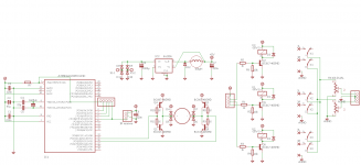
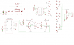
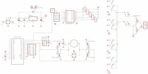
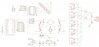
I attach the schematic below. It's quite simple. At the heart of the thing is an atmega328p. Those chipsets can be bought with the arduino bootloader. They can then be programmed in circuit with an arduino uno board.
It's connected to a IR receiver (on pin 5), to receive commands from an Apple remote. An H-bridge is connected to pin 15-16 (pwm outputs) to power and control the motor.
There's also an input selection section with relays (high sensitivy 5v ones from omron) but that one is simply controlled with a rotary switch. Remote source selection isn't something I use often.
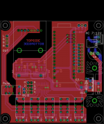
The whole thing is powered from a lm2956 switching regulator and fits on a 8*8cm board.
Does the overall schematic look ok ? Thanks in advance for any help on this.
There's a chinese kit floating around ebay for this (lite mv04) but the grounding is awful, the parts probably fake and source selection akward. So I'd rather build something myself.
I attach the schematic below. It's quite simple. At the heart of the thing is an atmega328p. Those chipsets can be bought with the arduino bootloader. They can then be programmed in circuit with an arduino uno board.
It's connected to a IR receiver (on pin 5), to receive commands from an Apple remote. An H-bridge is connected to pin 15-16 (pwm outputs) to power and control the motor.
There's also an input selection section with relays (high sensitivy 5v ones from omron) but that one is simply controlled with a rotary switch. Remote source selection isn't something I use often.
The whole thing is powered from a lm2956 switching regulator and fits on a 8*8cm board.
Does the overall schematic look ok ? Thanks in advance for any help on this.
Attachments
Arduino is very easy to implement. My remote preamp was my first Arduino project and my return to electronics since being a teenager.
Consider the Arduino Nano - a shrunk-down Uno, very cheap from China.
For relay switching a ULN2003A can be used – wish I’d known before using transistor/resistor/diode for my 6 input relays.
I use PGA2320 volume chip and am delighted with it.
However, with the lid off, my stripboard effort cannot compare to your PCB for looks.
Some additional alternatives for you:
https://github.com/mithat/RC5-preamp
https://github.com/mithat/Volume-AlpsRK16814MG
These are both my projects. I've flirted with making ready-to-go versions of them available for sale:
PreampControl | Mithat Konar's AudioPastures
VolumeA | Mithat Konar's AudioPastures
Currently they are not for sale, and I have no idea if I'll ever get around to offering them (or anything else!). If you decide to play around with the sources, I don't think I'll have time to offer any support for the next couple months. I'm just putting these out there in case you find them helpful.
If you do play around with these, all I ask is that you be respectful of the licenses.
Good idea on the nano. It doesn't take much more space and a Nano from China is actually cheaper than a preprogrammed atmega328p.Consider the Arduino Nano - a shrunk-down Uno, very cheap from China.
...
However, with the lid off, my stripboard effort cannot compare to your PCB for looks.
As for the looks, no big deal once the lid is closed
") I just like PCB for the ease of use.
I just like PCB for the ease of use.Thanks, I'll have a look. It seems more elaborate than I need but who knows ?Some additional alternatives for you:
...
If you do play around with these, all I ask is that you be respectful of the licenses.
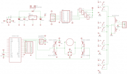
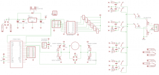
I've uploaded a new version of the schematic with some changes. I've replaced the atmega by a Nano and the discrete h-bridge by a l293dd.
Hifiduino has lots of info on the apple remote and there are lots of tutorials about controlling motors... that should be doable.
Attachments
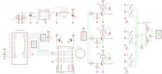
The uln2003 makes things a bit easier. While I was at it, I replaced the lm2596s by a good old lm7805. The average current draw is low enough and it's quite a bit cheaper.
Total BOM is 40€ at Mouser once VAT is added (pot and relays are 2/3 of that summ). With a 5€ arduino nano clone and 2€ for the pcb, the total project should end at about 50€, just a bit more expensive than the mv04.
Total BOM is 40€ at Mouser once VAT is added (pot and relays are 2/3 of that summ). With a 5€ arduino nano clone and 2€ for the pcb, the total project should end at about 50€, just a bit more expensive than the mv04.
Attachments
Hi Ben,
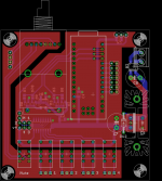
Nice board! If I may suggest, you could use analog pins A0-A7 as digital pins for motor control. It will make dedicated traces shorter unless you need a PWM control then pins D10 and D11 are a must. For the pin-header around pins D5-D7 I would provide complementary GND and/or +5V pins since digital pins should be referenced somewhere for operation (you need to connect a second wire somewhere). Also because the arduino has pull-up resistors on its pins built in you may wish to provide pull-down resistor pads should you need them. I would also add one more relay control output for power relay and extra header for the front panel power button. This way you can operate the entire integrated amp using your board as the standby controller. You have so much unused PCB space that you can further expand your project without increasing the boards size. For inspiration on the compact layout with lots of functionality you can have a look at my design.
Regards,
Oleg
Hi Ben, Nice board!
- If I may suggest, you could use analog pins A0-A7 as digital pins for motor control. It will make dedicated traces shorter unless you need a PWM control then pins D10 and D11 are a must.
- For the pin-header around pins D5-D7 I would provide complementary GND and/or +5V pins since digital pins should be referenced somewhere for operation (you need to connect a second wire somewhere). Also because the arduino has pull-up resistors on its pins built in you may wish to provide pull-down resistor pads should you need them.
- I would also add one more relay control output for power relay and extra header for the front panel power button. [...]
- Unused ULN2003 pins can be used to control the motor which would eliminate some more parts from the board...
Thanks a lot for the comments and ideas, that's really helpful.
- I must confess I didn't know I could use the analog pins as outputs.
Still, I'd rather keep the control lines on the PWM capable pins, just in case I want to play with the motor control.- Good catch, I'll add those pads. My first idea was to use those extra outputs to control the relays by remote if someone really wanted to. Just add three small links rather than a rotary switch.
- I've probably enough enough free space to add a pair of spst reed relays, that could be controlled by remote (buttons play and menu of the apple remote for example). That could indeed be useful in some situations.
- The problem with the uln2003 is once again Vce sat... It uses darlington inside and burns at least 0.9V. It could work if I raise the overall voltage of the PS to 6V or so... Gonna try that.
By the way, I've made a bom with Reichelt... it comes about 10€ cheaper than at Mouser. They don't stock the rk168 though but it's available on ebay at reasonnable prices.
Since you feed the board with the raw AC you can make another rectifier/filter/reg for the ULN2003 itself with 6VDC while powering the rest using 5VDC. On the other hand, according to the datasheets of alps pot and the relays you can go as low as ~4VDC and still be able to operate them. I operate 5VDC relays using the ULNs on 5VDC supply without problems.
PS: 0.9V dropout is at 100mA sink current per darlington pair... Relays need around 30~40 mA...
PS: 0.9V dropout is at 100mA sink current per darlington pair... Relays need around 30~40 mA...
Last edited:
Yes, agreed on the relays but, for the motor, I've got to add to the losses of the uln2003 the losses of the PNP transistors of the h-bridge. According to the uln2003 datasheet, the voltage drop is a typical 1.05V at 150ma (max motor draw). From a 5V supply, I'm borderline. It'd probably work though.
Using two lm7805/6 should be easy enough, they can share the same heatsink.
Or add a diode to the ground leg of the 7805 and another diode in the power line of the Nano...
Using two lm7805/6 should be easy enough, they can share the same heatsink.
Or add a diode to the ground leg of the 7805 and another diode in the power line of the Nano...
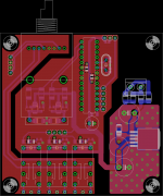
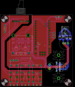
I made some changes.
- more exposed pins and ground headers to match;
- a fourth input relay;
- replaced the diodes by smd bridges;
- kept the discrete h-bridge (easier pcb layout), which means I can stay with a 5V supply for everything.
- more exposed pins and ground headers to match;
- a fourth input relay;
- replaced the diodes by smd bridges;
- kept the discrete h-bridge (easier pcb layout), which means I can stay with a 5V supply for everything.
Attachments
Serial spammer. Caught a very bad cold, so I'm stuck home with Eagle.
Last iteration I hope. One more relay squeezed on the board, that's 6 (only one empty spot on the uln2003 now ). Four for input switching, one for input muting, one for whatever auxilliary function one could need. The last two are remote controlled.
I also added small RC filters at the inputs, as RF filters.
Last iteration I hope.
One more relay squeezed on the board, that's 6 (only one empty spot on the uln2003 now ). Four for input switching, one for input muting, one for whatever auxilliary function one could need. The last two are remote controlled.I also added small RC filters at the inputs, as RF filters.
Attachments
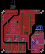
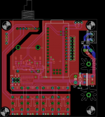
All right, this goes to the fab now.
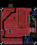
I've simplified things a bit. 5 input relays, 1 muting relay. Remote control for the volume and the muting, switching through a rotary switch for the input selection.
On the nano, D9-10 control the motor, D11 the muting, D12 gets the IR receiver.
I've simplified things a bit. 5 input relays, 1 muting relay. Remote control for the volume and the muting, switching through a rotary switch for the input selection.
On the nano, D9-10 control the motor, D11 the muting, D12 gets the IR receiver.
Attachments
- Status
- This old topic is closed. If you want to reopen this topic, contact a moderator using the "Report Post" button.
- Home
- Source & Line
- Analog Line Level
- Simple remote volume control (controlled through arduino)