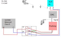
Sorry, I am still unclear now, thought I had it. I have made the distinction between where IEC and Pin1 connect to chassis and separated them as per the new diagram and your advice.
I don't need the safety connection from audio ground to chassis that you describe. I DO need to know how to reference the audio ground to allow my switch to work as per HYpex instructions. I thought we were there and agreed that a simple RC to chassis will help this as per dimdims post.
And my question is where to make this conection, I always thought that the 0V of my supplies will become the audio ground?
Attachments
If you don't want the safety connection from Audio Ground to PE protected chassis, then that is the end of it.
You don't need a chassis connection for the audio to work properly.
You can replace the chassis with a plastic box and your audio will work properly.
You can have no box at all and your audio will work properly.
If I am reading the correct Dimdim's post, then he too is confirming that the RCA to chassis connection is wrong and that following the AES48 connection information, given in the Hypex pdf, made his implementation quiet.
Last edited:
That is how I read Dimdims post too, but he tied the audio ground to chassis through a simple parallel RC network!
My questions are still:
1. I am tying two supply Ov's together so that the DAC on the Pi and the preamp share a common ground? This seems necessary and logical to me... correct?
2. I am tying the shell (audio ground) to chassis via a simple RC network as per hypex instructions - this is not entirely for safety but also to keep the reference voltage within the amplifier range, is this correct and do I need to strictly adhere to 100nf and 100ohm?
3. Still trying to figure this out.... audio ground for the Pi DAC combo will be the same as OV supply, therefore if I tie the regulated Ov outputs together as per question 1, then I can presumably tie this point to chassis through the RC network and only do this once as the audio signal will now have that connection to chassis as per question2?
sorry for so many questions but I feel I am getting there slowly,
stu
I don't know why the UcD instructions say that the RCA barrel should be connected to the chassis.
That is different from just about every other Builder/Designer.
Because it's what experts like Neil Muncy(RIP), Henry Ott and Jim Brown (and others) recommend.
No. Any connection to chassis should be for safety reasons only. You don't want the chassis to be part of the audio circuit. You need to be clear in your mind: 'audio ground' is the voltage reference point for audio signals (including unbalanced inputs), 'safety ground' keeps you alive. The only thing they have in common is the misleading word 'ground'.surfstu said:And then the only connection made to chassis by this audio ground is through a resistor capacitor network as shown in my updated diagram below. And this is to ensure that the common ground is at least somewhere near the operating range of the Amplifier for differential amplification.
A 100 ohm resistor has nothing to do with safety, as it won't pass a fault current. It appears that the Hypex instructions are based on the false idea that chassis should be the signal reference point. What you should do is connect the DAC and preamp signal ground to the power amp signal ground. Then, as a quite separate issue, you should connect the signal ground for the entire circuit to the safety ground, possibly via a loop breaker.2. I am tying the shell (audio ground) to chassis via a simple RC network as per hypex instructions - this is not entirely for safety but also to keep the reference voltage within the amplifier range, is this correct and do I need to strictly adhere to 100nf and 100ohm?
Ok, can I tie the common 0V from my two regulated supplies (one 5V for Pi Dac and the other dual +/-15V for preamp) all onto the UcD400 ground?
I read somewhere that the UcD modules are grounded to chassis anyway by way of their heatsinks?
Maybe this is why Dimdim achieved no Hum issues by referencing his unbalanced circuit to the chassis via the RC network
I read somewhere that the UcD modules are grounded to chassis anyway by way of their heatsinks?
Maybe this is why Dimdim achieved no Hum issues by referencing his unbalanced circuit to the chassis via the RC network
No, you must tie them together!surfstu said:Ok, can I tie the common 0V from my two regulated supplies (one 5V for Pi Dac and the other dual +/-15V for preamp) all onto the UcD400 ground?
If the module already connects its signal ground to chassis via the heatsink (a bad idea!) then the RC network is in parallel with a short, so does nothing.I read somewhere that the UcD modules are grounded to chassis anyway by way of their heatsinks?
Maybe this is why Dimdim achieved no Hum issues by referencing his unbalanced circuit to the chassis via the RC network
Why should he ?No, you must tie them together!
If the module already connects its signal ground to chassis via the heatsink (a bad idea!) then the RC network is in parallel with a short, so does nothing.
Not necessarily, since the module has balanced inputs which go into an instrumentation amplifier. As drawn, the signal ground of the preamp goes to the cold input, not to the ground of the ucd module which is left unconnected.
Unless of course, he tied the OV of the preamp and DAC to the OV of the UCD PS.
If the balanced inputs are implemented via a transformer then the various '0V' do not need to be connected. If via an instrumentation amplifier then some connection will be needed to keep within the valid input range. This connection has nothing to do with the chassis.
It can be difficult providing remote consultancy; if the requester can provide the accurate detailed information needed for good advice then he probably already knows enough to answer his own question.
It can be difficult providing remote consultancy; if the requester can provide the accurate detailed information needed for good advice then he probably already knows enough to answer his own question.
Agreed on the transformer.If the balanced inputs are implemented via a transformer then the various '0V' do not need to be connected. If via an instrumentation amplifier then some connection will be needed to keep within the valid input range. This connection has nothing to do with the chassis.
Agreed also that it has nothing to do with the chassis in theory but it doesn't hurt much to do it via the chassis either, especially with a resistor breaking ground loops (if the chassis is held at the same potential as the 0V of the amp).
Thanks DF96, am getting there on answering my own questions but lots of conflicting info, and I'm sure its all mostly correct but my confidence is not quite there yet!
I'm going to connect XLR pin 1 to chassis very near XLR
I'm going to connect IEC PE to chassis at another point near IEC as I am a noob and have no chance of achieving class II safety regs
I'm going to connect 0V output of regulator boards to 0V of SMPS400 supply
I will not connect my internal RCA circuit to chassis as per HYpex recommendations ( I think they recommend this only if designing class II insulation which is where some of my confusion has originated)
My 4pDT switch will switch between either 'hot and cold from XLR' or 'RCA Signal and RCA Ground' into the Hot and Cold inputs of the UcD400
Just read Your post 00940, Hypex gave me enough plastic spacers to mount the SMPS400. I have read that some people use one metal spacer to provide connection to chassis, I have also read that the UcD400 achieve chassis connection via their heatsinks, will ping it out with DVM to see if the modules are grounded to chassis. In which case I will just tie the 0V regulators output to chassis with 100ohm and small cap in parrallel
- Status
- This old topic is closed. If you want to reopen this topic, contact a moderator using the "Report Post" button.
- Home
- Source & Line
- Analog Line Level
- Signal to chassis ground query