i'm trying to emulate yamamoto dac which i believe takes balanced singal from the dac and unbalances it through a 2 transistor buffer.
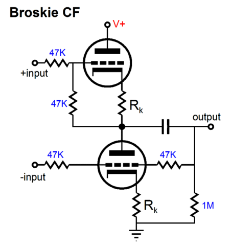
could something like broskie's cf work in a transistor form for the task, or should i look for something else?
i'm looking for something without gain and zero feedback, which opamps are not...
could something like broskie's cf work in a transistor form for the task, or should i look for something else?
i'm looking for something without gain and zero feedback, which opamps are not...
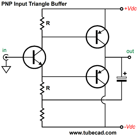
broskie cf and triangle buffer for reference. if i were to p2p the right half of the triangle buffer, how would i go about biasing the bjts?
i'm trying to emulate yamamoto dac which i believe takes balanced singal from the dac and unbalances it through a 2 transistor buffer...
My recollection is that the transistor version of the Yamamoto DAC simply ignores one of the current output phases of the D/A chip. I recall it utilizing metal cased PNP transistors configured in common-base for I/V conversion, tapping only one of the output phases per channel.
Well im only coming from this pic and their diagram but its clearly iout + & - to their output board. The same polarities are tied so theyre probably running the pcm chips in dual mono for more current. If non metal bjts are for i/v duty, as i assume, because the layout favors their location, the resistor values are weird because ones 600 other 2000... perhaps theyre intentionally doing it assymetrically for purely subjective benefits (different gains, different harmonic profile, combined you get 'richer' sound)
Seems simple and sounds good enough to emulate. The whole thing is so overpriced i should not feel bad copying it xD

Seems simple and sounds good enough to emulate. The whole thing is so overpriced i should not feel bad copying it xD
Agreed, the board labeling indicates that they take both phases. If the two metal cased transistors function as common-base I/V for each phase that leaves two plastic cased transistors performing some function. It 's just a guess, but I suspect they're configured as a current mirror pair. That would combine the anti-phase signal currents into an unbalanced single phase output.
Nothing screams "boutique component" like a wiring job like that. Awful. (They could've invested into some shielded audio cabling at least.) Oh, and huge film caps. Somebody should've told them that bending the legs of components right at the exit point is considered a Bad Idea, too. TBH, this looks like a kit assembled by someone with decent soldering experience but little actual knowledge.
It's very hard to guess what the circuitry might be like from the picture. Seems like there's two pairs of transistors of two different types per channel, so maybe a cascoded LTP? Or a balanced version of a 2-transistor amplifier circuit with collector output maybe?
It's very hard to guess what the circuitry might be like from the picture. Seems like there's two pairs of transistors of two different types per channel, so maybe a cascoded LTP? Or a balanced version of a 2-transistor amplifier circuit with collector output maybe?
- Status
- Not open for further replies.
- Home
- Source & Line
- Analog Line Level
- triangle buffer for unbalancing?