Hi,
I needed a cheap simple subwoofercross-over to be build into an old PA amp and bought one in China. I have reverse engineered it to see if I understand it. It's been a long time since I made any active cross-overs so I am very rusty.
So if you feel like it, could you have a look and comment? I asked for the schematics, but the seller couldn't deliver
Please note I did my best but I cannot guarantee I did not make any mistakes in drawing or reverse engineering. I haven't build it yet to make the reverse engineering simpler, so cannot comment yet if it even works. If you have any questions or think I did make a mistake and should check something, just let me know and I will obviously oblige.

Edit: as should be expected, I did do some work as well. Fixed the resistorvalue at the output of the third stage from 6k8 to 68k (my own mistake in reading the value on the PCB).
First stage is a buffer I guess. I find the 10k resistors somewhat smaller than expected since we don't know what will be driving it, but I'm not an expert. I think I may have a 10uF MKT to replace the bipolar (I mean electrolitic...) capacitor.
Found these on the website of Linkwitz Lab - Loudspeaker Design :

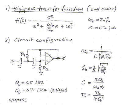
Second stage seems to be a 2nd order highpass filter. Frequency works out to be 49.8Hz (With R1 = 6k8, C=100n and R2=150k).

Hope I messed up the calculation and that should be 5Hz?
Or more likely: 6k8 should be 68k and it would result in a nice 16Hz highpass! (Which adheres to a suggestion found elsewhere that R2 = 2xR1)
Fourth stage:

But I cannot work out how the potentiometer fits in exactly. I'll try to find some more info in old magazines, but for now I understand even less than two days ago when starting this post.
I needed a cheap simple subwoofercross-over to be build into an old PA amp and bought one in China. I have reverse engineered it to see if I understand it. It's been a long time since I made any active cross-overs so I am very rusty.
So if you feel like it, could you have a look and comment? I asked for the schematics, but the seller couldn't deliver
Please note I did my best but I cannot guarantee I did not make any mistakes in drawing or reverse engineering. I haven't build it yet to make the reverse engineering simpler, so cannot comment yet if it even works. If you have any questions or think I did make a mistake and should check something, just let me know and I will obviously oblige.

Edit: as should be expected, I did do some work as well.
First stage is a buffer I guess. I find the 10k resistors somewhat smaller than expected since we don't know what will be driving it, but I'm not an expert. I think I may have a 10uF MKT to replace the bipolar (I mean electrolitic...) capacitor.
Found these on the website of Linkwitz Lab - Loudspeaker Design :

Second stage seems to be a 2nd order highpass filter. Frequency works out to be 49.8Hz (With R1 = 6k8, C=100n and R2=150k).
Hope I messed up the calculation and that should be 5Hz?
Or more likely: 6k8 should be 68k and it would result in a nice 16Hz highpass! (Which adheres to a suggestion found elsewhere that R2 = 2xR1)
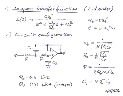
Fourth stage:

But I cannot work out how the potentiometer fits in exactly. I'll try to find some more info in old magazines, but for now I understand even less than two days ago when starting this post.
Last edited:

Turns out the frequency adjust potmeter is NOT grounded in the schematic, but it IS on my PCB...
My assumption on the highpass not being 50Hz but 16Hz due to a wrongly printed value is wrong according to this schematic.
Any insights as to why it was designed like this? I could not (yet) find a better schematic as the PCB from this seller isn't available anymore.
Last edited:
- Status
- This old topic is closed. If you want to reopen this topic, contact a moderator using the "Report Post" button.