What would happen if a Fault Current of 1000Apk tried to pass through your ground lift ("gnd lift")?Hi Andrew. I already used a bipolar cap, and I installed a gnd lift of 100R/0.1uF in parallel between the audio ground and the chassis, safety ground.
Thanks
SB
I'll have to make some repair. From my experience, in home away from the proffesionnal stadium style sono system, 1000Amp current ground loop will never happen ") . My house electrical system is 400Amp, two phases, which means maximum 200Amp per phase, and all my sound system have dedicated 15Amp breakers and ac outlet. I'll never see more then 15amp...
. My house electrical system is 400Amp, two phases, which means maximum 200Amp per phase, and all my sound system have dedicated 15Amp breakers and ac outlet. I'll never see more then 15amp...
SB
. My house electrical system is 400Amp, two phases, which means maximum 200Amp per phase, and all my sound system have dedicated 15Amp breakers and ac outlet. I'll never see more then 15amp...SB
Sorry but that is not correct. There will be way higher currents for a very short time (but they may be disastrous).
Wow ! Where were you when we needed a marketing guy ?
For the ones not familiar with the Subbu DAC, well it is a killer little DAC, excellent sounding. It uses the self contains ESS ES9023 DAC (no output op-amp needed) and the excellent Wolfson WM8804 SPDIF digital receiver. The WM8804 uses advanced jitter attenuation PLL with low intrinsic jitter, and is compatible with 24bits/192kHz. Even if it a very small footprint DAC board, it is very well designed, with CLC filtered pre-filters and separate regulators for all supplies. Extensive listening was done for every part selection and the PCB layout is optimized for the best sound. The DAC itself is mounted into a shielded Mu-metal enclosure. An external dedicated power supply, also designed for the lowest noise possible provides the +5V DAC supply. All in all, it is a great sounding DAC.
Wow ! Where were you when we needed a marketing guy ?
Have a proper look at your distribution board MCBs.I'll have to make some repair. From my experience, in home away from the proffesionnal stadium style sono system, 1000Amp current ground loop will never happen
SB
They will have marked on them the rated breaking capacity.
That breaking capacity is the maximum current that the MCB can break during a mains to return Fault incident.
It is usually from 5kA to 15kA.
That is the potential current that can pass through your Fault Current route if you have a catastrophic failure in your mains powered equipment.
If some component in your Fault Current route vaporises before your mains fuse or the MCB have ruptured/opened, then you can have an apparently dead piece of equipment that is actually LIVE. It could kill anyone that touches it if the case is also Live.
Every component in your Fault Current route MUST SURVIVE long enough for the mains fuse to rupture and the arc to extinguish.
It is the opening of the mains fuse that stops the faulty equipment case becoming LIVE.
Complete and utter rubbish !I'll never see more then 15amp...
Last edited:
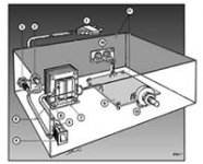
After some thought I don't see the problem as it can be clearly seen on the pictures that the chassis is directly connected to PE (as it should be!). The "ground lift" is only to reference audio GND to PE without the drawback of a ground loop. I am fine with that and build my stuff the same way. In the old days audio ground was called "massa" over here and PE (protective earth) was called "aarde" which means earth. Nowadays both are called "ground" which makes things unclear for many I have noticed. Here it is not required to connect a device GND to PE under a certain number of power the device consumes.
In some countries audio GND is always directly tied to PE as local regulations may say so. You might see more than the average number of ground loop problems in such areas. People that are educated in such areas will always tell you to connect audio GND directly to PE and everything else is considered dangerous in their book.
Please consider how likely the chance is that a L or N wire breaks and touches the audio GND. It will much more likely touch the chassis the way careful builders build their stuff. Still, don't take anything for granted and always take the time to check safety of your device and stay away from user unfriendly and/or unsafe practices. End users might have different ideas on how to switch on the device you built. I have more than once seen burnt woofers as a muting circuit was omitted and one of the family members choose to switch on the power amp first and the preamp later. Just an example.
Consider investing some minutes in examining the way breakers and short circuit currents work. There can be thousands of Amperes short circuit current for milliseconds before the breaker trips (also in quite modest domestic installations). Never underestimate the power of electricity.
In some countries audio GND is always directly tied to PE as local regulations may say so. You might see more than the average number of ground loop problems in such areas
. People that are educated in such areas will always tell you to connect audio GND directly to PE and everything else is considered dangerous in their book.Please consider how likely the chance is that a L or N wire breaks and touches the audio GND. It will much more likely touch the chassis the way careful builders build their stuff. Still, don't take anything for granted and always take the time to check safety of your device and stay away from user unfriendly and/or unsafe practices. End users might have different ideas on how to switch on the device you built. I have more than once seen burnt woofers as a muting circuit was omitted and one of the family members choose to switch on the power amp first and the preamp later. Just an example.
Consider investing some minutes in examining the way breakers and short circuit currents work. There can be thousands of Amperes short circuit current for milliseconds before the breaker trips (also in quite modest domestic installations). Never underestimate the power of electricity.
Last edited:
After some thought I don't see the problem as it can be clearly seen on the pictures that the chassis is directly connected to PE (as it should be!). The "ground lift" is only to reference audio GND to PE. I am fine with that and build my stuff the same way.
In some countries audio GND is tied to PE. You see a lot of ground loop problems in such areas.
Still consider investing some minutes in examining the way breakers and short circuit currents work. There can be thousands of Amperes short circuit current for milliseconds before the breaker trips (also in domestic installations).
The only reason we connect the Main Audio Ground to Chassis is to comply with:
all exposed conductive parts should be connected to the protected chassis.
Why do we need that?
What is it achieving?
What might happen if we did not do that?
Here's a simple senario:
The mains live wire comes loose from the terminal block fitted AFTER the mains fuse. The springy live wire flicks across and touches a metal component next to it. (the back panel is full of metal components).
That metal component is now LIVE. Touch it and you could be DEAD !
It's the Fault Current flowing from Mains Live through anything connected to the Protected Chassis and thence back to the distribution board that blows the fuse (or opens the MCB).
It is advisable for DIY builders to use IEC sockets with built in fuse holder. Sorry Andrew but the UK regulations differ in that aspect from the local regulations here. More than once I have solved technical problems in unsafe built UK audio devices, correcting the errors and removed the GND to PE connections as it was causing loops. More than once I have seen live 240 V wires a few mm from exposed conductors. More than once I have had UK built devices blowing up in my lab because of design errors or severely underrated parts. Nothing against the UK but please stop thinking the UK leads the world in safety. Many of its citizens seem to think so.
I build stuff for more than 30 years now and learnt that PE causes more audio problems than it solves. We do need to build devices very safe though. Build carefully and connect cases to PE is the way to go for good sound and safe devices. Here it was a very good habit of Elektor magazine to print safe practices according local regulations in every single magazine. Many dutch builders refer to those pages and many know the drawing as attached. Elector is so kind to publish the info on their web page:
https://www.elektormagazine.nl/articles/zelfbouw-en-veiligheid/6537
BTW if all exposed conductive parts must be connected to PE the device won"t work and the device itself would be a short circuit by definition
Attachments
Last edited:
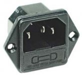
Please note that I am not the expert to tell someone what to do. We are all in the same boat with DIYing audio electronics. There are local regulations that must be followed as a minmum standard. However it would be nice of these fused connectors would be standard in devices, be it DIY or factory built. IMHO these are safer than separate chassis mount fuse holders. They make wiring easier too. Just be sure you buy tested and certified versions and not ultra cheap unbranded asian ones that might not be short circuit proof. The branded ones often have the connections covered in plastics and the cheap knockoffs have exposed conductors at the backside which is counterproductive with regards to safety.
C14 connectors are rated for 10 A max....
Back to the subject: you built a fine device sir !
C14 connectors are rated for 10 A max....
This the complete preamp inside view. The sound is very good and the builtin Subbu Dac is a plus for sure. There is no such thing a simple full function line preamp
Back to the subject: you built a fine device sir !
Attachments
Last edited:
PE is not there to improve audio quality.I build stuff for more than 30 years now and learnt that PE causes more audio problems than it solves.
Don't make the mistake of confusing audio for safety.
PE is solely there for safety.
Connecting the chassis to all/any exposed conductive parts is there purely for safety.
The rule is not there to improve audio quality.
You JP seem to be sending a confusing message to all your readers because you are mixing up the safety function with something else.
Here is another example of where you have mixed up the functions
PE has NOTHING to do with improving sound quality.connect cases to PE is the way to go for good sound
PE is not there to improve audio quality.
Don't make the mistake of confusing audio for safety.
PE is solely there for safety.
Connecting the chassis to all/any exposed conductive parts is there purely for safety.
The rule is not there to improve audio quality.
You JP seem to be sending a confusing message to all your readers because you are mixing up the safety function with something else.
Here is another example of where you have mixed up the functions PE has NOTHING to do with improving sound quality.
Hi AndrewT, I think you forgot to read some sentences which gives confusing reactions to "all my readers"... PE is of course solely for safety but it can also give audio problems certainly when directly connecting audio GND to PE. So we need to make it safe and good sounding (which is the purpose of our hobby if I am not mistaking) which leads to connecting the chassis directly to PE and keep audio GND either floating or (preferably) "lifted" with adequately rated parts. This is fully accepted in many countries except yours. Connecting DIY stuff safely to 230V should be done with the utmost attention to detail and all possible failures should be taken into account. When those conditions can not be met one should not even attempt to build stuff. I agree with you that devices must be safe, it would be nice if we could make a section here with how to build stuff the safe way. Be it EU style and/or the UK style. I see a challenge here ! The non-challenge way is to report my post as I am likely promoting unsafe behavior in your book but it all depends on a countries minimal standards/regulations and those might differ in various countries.
There, I fixed it for you:
I build stuff for more than 30 years now and learnt that PE causes more audio problems than it solves. We do need to build devices very safe though. Build carefully and connect cases to PE is the way to go for good sound and safe devices.
BTW connecting all exposed conductors to PE will make it a non working device. It will be an excellent device to test the circuit breakers of the house.
* This discussion is threadjacking in a way. If we are grown up men we should start a new thread as these issues turn up every now and then and it is not the first time our names are in those discussions. We could join forces and start a "How to build mains connected gear safely" thread and ask the guys to make it a sticky. That way we contribute instead of repeating ourselves.
Last edited:
Ive been thinking about building the Borbely All JFET Pre, where did you get the PCB from? And youve done some really nice work there..
He bought the complete preamp from me.
Another member
'ticknpop' mailbox is full
You can get some of the lower current output preamps / Borbely boards from jim’s audio on Ebay.
LB audio /( Les Bordelon) has the high current one , whether he’ll sell boards and schematics is up to him.
And finding the correct idss jfets, matched pairs, and Mostfets isn't easy unless you’ve been hoarding them like me.
LB audio /( Les Bordelon) has the high current one , whether he’ll sell boards and schematics is up to him.
And finding the correct idss jfets, matched pairs, and Mostfets isn't easy unless you’ve been hoarding them like me.
SB it seems a shame to AC couple the Borbely preamp through an electrolytic cap. The Borbely system I run is totally DC coupled all fet/jfet from dac or phono input to power amp output. The power amp uses Borbely’s dc protect / mute delay board for DC protection - the protection board design is in the Borbely DC 102 article. If you want to protect the preamp output from DC output and avoid any capacitor coupling you can use the DC 102 protect board and make it more sensitive by adjusting the reference voltage setting resistors to maybe 10 to 50mv. It also gives you a mute delay for turn on.
Don’t increase the value of any of the power suppy Electrolytic capacitors on the DC 102 DC protect board like any diyaudio guy would normally do. The cap values are delibereratly small so it turns off (mutes) right away when the preamp is turned off or the AC power fails. The input to the protect board can be a 10uf /63 volt polyester instead of the back to back 22uf/40 volt electrolytics.
Updates to the preamp design are to use OPA 140 or AD 4625 op amps for the servo. They have 1/5 or less than the noise of the AD 820. Replace the 33K2 current source resistor for the VAS cascode with a E102 jfet current source diode. Replace the VAS cascode’s LM385 voltage references with 2 series connected green LEDs ( not blue ones like Erno first used, they are too noisey).
Last edited:
You can get some of the lower current output preamps / Borbely boards from jim’s audio on Ebay.
LB audio /( Les Bordelon) has the high current one , whether he’ll sell boards and schematics is up to him.
And finding the correct idss jfets, matched pairs, and Mostfets isn't easy unless you’ve been hoarding them like me.
Les Bordelon now sells his own designs, inspired by Borbely I think, and this probably eliminates the problem of sourcing legacy Toshiba devices.
- Status
- This old topic is closed. If you want to reopen this topic, contact a moderator using the "Report Post" button.
- Home
- Source & Line
- Analog Line Level
- My Borbely All-Fet Preamp with Subbu DAC