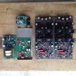
Hi. In the next post I'll present my newly completed Borbely All-Fet Preamp with Subbu built-in DAC. I'll try to explain the complete built process to give you an idea of the complexity of a line preamp.
At first I was lucky enough to buy from the Swap Meet a Borbely All-Fet preamp stereo PCB with all the options, Teflon PCB, Caddock & Dale resistors, Black Gate & Wima capacitors. The treat")
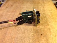
I already had the Subbu and its pcb in stock that was waiting to be put to good use. I decided to install it inside the preamp, hence it will have a digital input option built-in. The Subbu DAC itself will be mounted inside a nice little mu-metal shielded enclosure to prevent noise contamination inside the preamp.
For the volume I was lucky enough to get a nice Muse stereo controller that supports IR remote control. It has a Mute function, IR code learning mode and we can set the starting volume.
Finally I had a nice enclosure that I bought years ago from an other member. I was planning to build a PassLabs preamp inside it, but since I built my XP-20 clone, it was not needed. I decided to use it for the Borbely.
So this is what I had at the beginning, but I was far from a complete preamp
At first I was lucky enough to buy from the Swap Meet a Borbely All-Fet preamp stereo PCB with all the options, Teflon PCB, Caddock & Dale resistors, Black Gate & Wima capacitors. The treat
I already had the Subbu and its pcb in stock that was waiting to be put to good use. I decided to install it inside the preamp, hence it will have a digital input option built-in. The Subbu DAC itself will be mounted inside a nice little mu-metal shielded enclosure to prevent noise contamination inside the preamp.
For the volume I was lucky enough to get a nice Muse stereo controller that supports IR remote control. It has a Mute function, IR code learning mode and we can set the starting volume.
Finally I had a nice enclosure that I bought years ago from an other member. I was planning to build a PassLabs preamp inside it, but since I built my XP-20 clone, it was not needed. I decided to use it for the Borbely.
So this is what I had at the beginning, but I was far from a complete preamp
Attachments
Last edited:
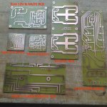
Then I had to figure out what was missing, and to build the needed PCB assy.
First the preamp supply. I didn't bought the original Borbely high current rectifier and mute pcb and the custom power transformer.
For the transformer I went the dual mono route, using nice Amveco 12.5VA per channel. But I needed a pcb to mount them...
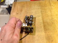
Then I needed an hardware mute delay to let the Borbely preamp servo settle at start-up. The original Borbely rectifier pcb was providing that. I also need an auxiliary supply isolated from the Preamp & Muse for the controller display. I also decided to use as much of my pcb leftover pcb material as possible. Here came the small auxiliary 12V supply and Mute timer.
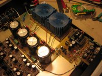
Then to supply the preamp, my own replica of the Borbely high current rectifier PCB with Hexfred rectifiers and Nichicon Muse Gold KG filtering caps.
An other PCB was needed.
The rear connectors Input/Output connectors selection and routing was needed. Instead of having the input signal going around inside the preamp, and without a controller for the input selection, I decided to use a nice Elma input selectot switch I had in stock for the inputs selection. And a custom pcb installed on the back with take care of the In/out duty and the output Mute relay.
Finally the enclosure I use had a separate Tape output selector, dawn i needed to cover for that as well Then I decided to use a front rotary switch, coupled by flat cable to the back, where the inputs will be selected for the Tape output. An other PCB
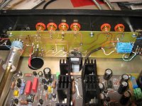
You can see here all the PCB I made
First the preamp supply. I didn't bought the original Borbely high current rectifier and mute pcb and the custom power transformer.
For the transformer I went the dual mono route, using nice Amveco 12.5VA per channel. But I needed a pcb to mount them...
Then I needed an hardware mute delay to let the Borbely preamp servo settle at start-up. The original Borbely rectifier pcb was providing that. I also need an auxiliary supply isolated from the Preamp & Muse for the controller display. I also decided to use as much of my pcb leftover pcb material as possible. Here came the small auxiliary 12V supply and Mute timer.
Then to supply the preamp, my own replica of the Borbely high current rectifier PCB with Hexfred rectifiers and Nichicon Muse Gold KG filtering caps.
An other PCB was needed.
The rear connectors Input/Output connectors selection and routing was needed. Instead of having the input signal going around inside the preamp, and without a controller for the input selection, I decided to use a nice Elma input selectot switch I had in stock for the inputs selection. And a custom pcb installed on the back with take care of the In/out duty and the output Mute relay.
Finally the enclosure I use had a separate Tape output selector, dawn i needed to cover for that as well
Then I decided to use a front rotary switch, coupled by flat cable to the back, where the inputs will be selected for the Tape output. An other PCB You can see here all the PCB I made
Attachments
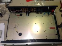
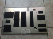
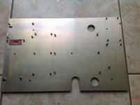
With all these PCB to install into the preamp, I decided to install a sub mounting plate inside. All the PCB will be fix to this plate and only a few standoff will hold the plate inside the preamp. I can also use this plate as insulation for the signal cables that will be routed underneath. This plate was treated with vibration absorption pads to prevent vibration.
Attachments
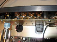
The Muse controller used for Volume is has good as its supplies. The Muse controller doesn't have built-in pre-regs and it needs +/-15V. I used the already available +/-24V full discrete low noise supplies from one channel of the Borbely preamp to supply +/-15V pre-regs mounted on a separate PCB on the Muse controller. The pre-regs have CRC pre-filter for the lowest noise supply possible
The controller can control a I2S display, but the display is noisy and will pollute the preamp and Muse supplies. To prevent that I use a I2S magnetic insulator and a separate 5V supply that I produce from the auxiliary 12V Mute supply.
I mounted this small pcb on the Muse Controller.
The controller can control a I2S display, but the display is noisy and will pollute the preamp and Muse supplies. To prevent that I use a I2S magnetic insulator and a separate 5V supply that I produce from the auxiliary 12V Mute supply.
I mounted this small pcb on the Muse Controller.
Attachments
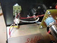
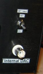
This is the Subbu DAC and its supply installed inside the preamp. I use a DPDT switch on the preamp back to select the Input 1 source, normal analog Single-ended input or the Supply output. The DAC has an insulated SPIDF BNC connector on the back as well.
For the ones not familiar with the Subbu DAC, well it is a killer little DAC, excellent sounding. It uses the self contains ESS ES9023 DAC (no output op-amp needed) and the excellent Wolfson WM8804 SPDIF digital receiver. The WM8804 uses advanced jitter attenuation PLL with low intrinsic jitter, and is compatible with 24bits/192kHz. Even if it a very small footprint DAC board, it is very well designed, with CLC filtered pre-filters and separate regulators for all supplies. Extensive listening was done for every part selection and the PCB layout is optimized for the best sound. The DAC itself is mounted into a shielded Mu-metal enclosure. An external dedicated power supply, also designed for the lowest noise possible provides the +5V DAC supply. All in all, it is a great sounding DAC.
For the ones not familiar with the Subbu DAC, well it is a killer little DAC, excellent sounding. It uses the self contains ESS ES9023 DAC (no output op-amp needed) and the excellent Wolfson WM8804 SPDIF digital receiver. The WM8804 uses advanced jitter attenuation PLL with low intrinsic jitter, and is compatible with 24bits/192kHz. Even if it a very small footprint DAC board, it is very well designed, with CLC filtered pre-filters and separate regulators for all supplies. Extensive listening was done for every part selection and the PCB layout is optimized for the best sound. The DAC itself is mounted into a shielded Mu-metal enclosure. An external dedicated power supply, also designed for the lowest noise possible provides the +5V DAC supply. All in all, it is a great sounding DAC.
Attachments
Last edited:
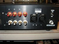
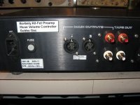
This the rear Input/Output & Mute PCB. It uses an Elma dual pole rotary switch for source selection, very short path to the input connectors using resistors legs wire connection (CFM55 Dale resistor legs were used for the connection). It also has the Tape selection flat-ribbon socket and the Output Mute relay.
I use CMC RCA connectors. The preamp is Single-Ended only but the chassis I have has provision for balanced XLR In/Out connector.
I decided to installed them for convenience only. The Balance input is 'Pseudo Balance Only' and has only pin2 (+) & gnd connected.
The Output is only Pin2 and Pin3-Gnd are shorted. They are ready to connect to a PassLabs amp for example.
When you use a input selector switch on the preamp back it is always a good thing to use a flexible shaft coupler between the switch and the front connecting rod. With DIY there is always some error between switch and front button axis, and the flex coupler take care of that. I got mine from Mouser, from Adafruit, Part 485-1176
Attachments
Last edited:
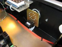
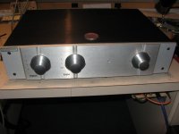
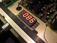
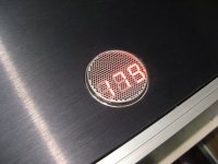
The Muse controller supports an external I2S display. It shows the volume setting, flash on/off when in mute and it is used to display the IR code learning mode sequence. I didn't want to drill the front panel, hence I installed the display so it can be seen from a top cover small ventilation vent.
As the Muse controller told me, the display adapter can cause preamp supplies noise contamination, and that was the case here. I planned in advance and the 12V Mute auxilliary supply was used to supply a separate and floating 5V supply for the Display only. The I2S controller signal is routed using a ADUM1250A I2S magnetic insulator, that decouple completely the preamp supply from the display ones, solving the noise problem.
As the Muse controller told me, the display adapter can cause preamp supplies noise contamination, and that was the case here. I planned in advance and the 12V Mute auxilliary supply was used to supply a separate and floating 5V supply for the Display only. The I2S controller signal is routed using a ADUM1250A I2S magnetic insulator, that decouple completely the preamp supply from the display ones, solving the noise problem.
Attachments
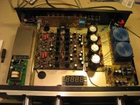
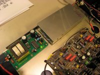
Here the supply PCB completed, preamp dual mono transformers, high current HEXFRED rectifiers and auxiliary 12V supply and Mute timer. This pcb is also use to supply the front blue power-on led.
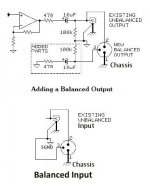
You could use pin2 for signal hot and pin3 for signal return as the unbalanced output. (your back plate label states "Pin 3 N/C")This the rear Input/Output & Mute PCB. It uses an Elma dual pole rotary switch for source selection, very short path to the input connectors using resistors legs wire connection (CFM55 Dale resistor legs were used for the connection). It also has the Tape selection flat-ribbon socket and the Output Mute relay.
I use CMC RCA connectors. The preamp is Single-Ended only but the chassis I have has provision for balanced XLR In/Out connector.
I decided to installed them for convenience only. The Balance input is 'Pseudo Balance Only' and has only pin2 (+) & gnd connected.
The Output is only Pin2 and Pin3-Gnd are shorted. They are ready to connect to a PassLabs amp for example.
When you use a input selector switch on the preamp back it is always a good thing to use a flexible shaft coupler between the switch and the front connecting rod. With DIY there is always some error between switch and front button axis, and the flex coupler take care of that. I got mine from Mouser, from Adafruit, Part 485-1176
That leaves pin1 connected to chassis.
The outputs then become compatible with any/every conventionally wired XLR balanced impedance cable.
If you want, the Pin3 can be converted to balanced impedance using the passive circuit in Jensen an003 section 2.4 "a simple alternative".
This would be compatible with both balanced and unbalanced XLR cable to either balanced, or unbalanced inputs of the receiver.
The extra resistance of the "simple alternative" in the signal return line is of little consequence if you keep it's value low, anywhere from 10r to 51r would be OK.
A correctly wired "conventional" XLR balanced impedance cable should have Pin1 to shield/screen at both ends, Pin2 signal hot, Pin3 signal cold.
Last edited:
So Andrew it should looks like this for the Input/Output?
My preamp has no 100K from Out to ground at the output. Should I install one so it matched the pin3 side on the output?
Also my preamp uses a Servo, hence there is no coupling cap at the output.
And my preamp signal ground is not connected to chassis either.
My preamp has no 100K from Out to ground at the output. Should I install one so it matched the pin3 side on the output?
Also my preamp uses a Servo, hence there is no coupling cap at the output.
And my preamp signal ground is not connected to chassis either.
Attachments
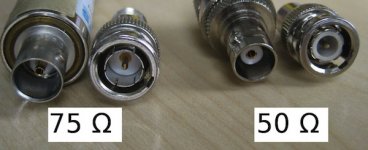
Because I use mostly 50ohms coax cable, because it is a little DAC, and I reserved the full 75 ohms, coax & cable for my big DAC, and because the impedance mismatch that degrade the signal, and increase the jitter is removed a great deal by the excellent Wolfson receiver, not counting the excellent jitter tolerance of the ESS dac chip.
I found that the meticulous respect to standard of 75ohms of the SPDIF is more acute with older digital receiver, such as the Cirrus Logic ones.
I tried the 75ohms BNC, but I couldn't hear a difference with the Subbu, driven at 24/192Khz by my music server and an M2Tech USB converter. Anyway my USB converter is using a normal 50ohms BNC as well...
I have only 75ohms BNC on my top Mark Levinson DAC and Transport, and a few of my top DAC. The small ones still use 50ohms connectors.
Hence I used the 50ohms that I have more in stock.
Hi Andrew. Greats suggestions, I'll implement them for sure
Merlin, it sounds great
Thanks again
SB
I'm glad you enjoy the preamp.
Cheers
Felipe
The 100k can have two uses.So Andrew it should looks like this for the Input/Output?
My preamp has no 100K from Out to ground at the output. Should I install one so it matched the pin3 side on the output?
Also my preamp uses a Servo, hence there is no coupling cap at the output.
And my preamp signal ground is not connected to chassis either.
To carry any capacitor leakage current to ground.
To define the signal to audio ground impedance.
For both uses the 100k value is not critical. It could be much higher or much lower. I think you should retain some value. Match them to better than 1% (<0.1% if you can).
The electrolytics defeat your DC input. You should consider whether your out/in works with/without and whether omitting them is better.
Read Jensen's note re decreasing the series resistor and increasing the cap value and going to bi-polar.
There is probably a Main Audio Ground to Chassis connection somewhere. Measure to check.
Last edited:
- Status
- This old topic is closed. If you want to reopen this topic, contact a moderator using the "Report Post" button.
- Home
- Source & Line
- Analog Line Level
- My Borbely All-Fet Preamp with Subbu DAC