There may be a drafting error in your schematic, in the vicinity of the OPA1632. Is it possible that the circuit TINA is simulating, has a different topology and different component values than the schematic attached to post #20? A quick glance at the OPA1632 datasheet suggests that correct operation requires a different circuit than the one shown here.
Can you explain a bit further? I do want to make educated transistor selection decisions, but time is limited. Moreover, the amp currently works rather well, even on a breadboard, even on a 9v battery supply; I did post audio.
One note: Power supply will likely be increased a fair bit.
Power supply failures of one rail can cause issues with regular opamps - NE5532 (per Doug Self) and DOA's - JE-990C incorporates additional diodes to deal with that issue specifically. See John Hardy's notes in the 990.pdf that Mark linked to.
Second most DOAs are targeted at microphone preamps where extra voltage means lower distortion and higher S/N as well as significantly higher current drive into lower impedances. In Small Signal Design, Doug Self explains that's why he makes +-17V power supplies. He also shows the design of a typical mixer console supply with shutdown should one rail fail.
Third, API created the VPR standard and GroupDIY created the 51x standard, voltages tend to center around +-16.5 VDC. VPR is only +-16VDC. 51X is +-16.5 VDC (0.5VDC to account for protection diode drop) and +-24 VDC.
And most of the DOAs were designed back in the late 1970s and early 1980s. The JE-918 and JE-990 being prime examples. Thus were designed for +-24 VDC max. The transistors needed a high enough voltage to withstand failures that might cause 48 VDC to occur. A 5087 is good up to 50 VDC while the PN4250A is good up to 60 VDC.
In addition, on the PNP side, the 5088 is only a 30V device. Thus the PN2484, which is from the same process as the 5088 and a 60V device.
Most current DOAs use the BC550/560 pair today. Even Sam Groner when he can't get Toshiba or other 2SC parts. Though he does use the 2N4401/4403 when noise is important and voltages aren't too high.
Under +- 20VDC the 4401/4403 pair will have less noise - but the hfes are a bit apart. The ones I've measured and sorted tend to have much higher hfes than the datasheet declares - On Semi sot23 devices. The PN2484/PN4250A devices are spec'ed at 2 dB, the same as the BC550C/560C devices. Though the data sheet declares higher minimum hfe's for the BC550C/560C.
Spec wise, the BC550C/560C is somewhat better when looking at the data sheet.
I suspect most tend to use the BC550C/560C today mainly because of momentum - it's the easy choice, the devices perform well, and tend to match the spec sheet.
Mark, probably I took some liberties I shouldn't have. The OPA1632 was supposed to be an easy solution to providing differential output drive even though I've never worked with a fully differential IC amp before. Rather than fiddling with it, can I replace it with a pair of emitter followers or darlington pairs prior to the AC coupling and call it a day?
Shadow, I see what you're saying - there's no possibility of that much voltage across any transistor in this design, so the current transistors will stay (although I do have some 2N4401s on hand to experiment with).
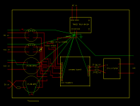
On the subject of supply voltage and it's correlation with distortion, here's a conceptual drawing of the main board showing the PSU idea. An LT3080 in adjustable configuration regulates the switchmode module for an output of 9 to 18 or 20 volts. One of the Vrefs sits at half the regulated output, while the other is for something else.
I don't think aliasing is a concern, despite the TRACO's switching frequency sitting ominously 4kHz above my typical sample rate. Ripple and noise in the TRACO is <100mV and the LT3080 shows 50dB ripple rejection at the switching frequency, though it falls quickly above it. Factor in the additional rejection in the preamps, analog antialiasing, oversampling ADC with digital decimation and sheer force of will. Safe?
Also note the pin headers and transformer selection switch at the inputs. Is this asking for trouble?
Finally, I should note that the destination is Japan, which notoriously lacks grounded outlets.
Shadow, I see what you're saying - there's no possibility of that much voltage across any transistor in this design, so the current transistors will stay (although I do have some 2N4401s on hand to experiment with).
On the subject of supply voltage and it's correlation with distortion, here's a conceptual drawing of the main board showing the PSU idea. An LT3080 in adjustable configuration regulates the switchmode module for an output of 9 to 18 or 20 volts. One of the Vrefs sits at half the regulated output, while the other is for something else.
I don't think aliasing is a concern, despite the TRACO's switching frequency sitting ominously 4kHz above my typical sample rate. Ripple and noise in the TRACO is <100mV and the LT3080 shows 50dB ripple rejection at the switching frequency, though it falls quickly above it. Factor in the additional rejection in the preamps, analog antialiasing, oversampling ADC with digital decimation and sheer force of will. Safe?
Also note the pin headers and transformer selection switch at the inputs. Is this asking for trouble?
Finally, I should note that the destination is Japan, which notoriously lacks grounded outlets.
Attachments
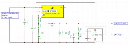
And here's the PSU schematic. LT3080 regulates the switchmode supply. Vout is variable from 10.5 to 20.5VDC. The 220uF cap is an absolute maximum for the TRACO. The LT3080 is set up according to the application notes and schematics. There's no maximum output capacitance listed for it, but just I used the values from the "lab supply" schematic. If it's good enough for the lab...
Reference voltages (only one is shown) are courtesy of an LM4562 opamp. Wasteful, maybe, but it ticks more boxes than anything else I have on hand.
What I'm unclear on is how bypassing works in the absence of ground. Do switching supply outputs usually ripple in phase or inverted? If the bypassing is good enough, does it even matter since all the supply and reference rails will be at or close to the same A/C potential? I'll string a technical ground wire right out the apartment window if I have to (not true), but it would be most beneficial for the circuit to function well without it.
Attachments
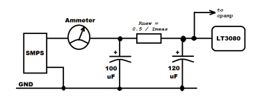
There's a 220uF capacitor on the SMPS output. You could split that into two capacitors and put a resistor between, thereby making a "pi" filter to reduce ripple at the input of the LT3080. I recommend sizing the series resistor so the voltage dropped across it is about half a volt.
_
_
Attachments
Even though I've included it in many of these schematics, there will not be an actual earth ground to bypass ripple to. Correct me if I'm wrong, but it seems that as long as the rails are rippling at the exact same A/C potential, all is well thanks to the common mode rejection of the transformers.
I will most certainly try out the pi filter. In fact, I'm going to go ahead and put in the Mouser order, get the rest of this stuff built and whip out the oscilloscope.
By the way, Mark and everyone who has contributed this far, I really do appreciate you helping me out in my amateur hour of need.
I will most certainly try out the pi filter. In fact, I'm going to go ahead and put in the Mouser order, get the rest of this stuff built and whip out the oscilloscope.
By the way, Mark and everyone who has contributed this far, I really do appreciate you helping me out in my amateur hour of need.
While waiting for parts, I got an uneasy feeling about the opamp pre's single ended output and called Jensen - the engineer recommended a 220uF cap (on the + side of the primary, incidentally) to avoid a significant low-end resonance peak and rolloff. So that's crazy and imperils the build philosophy (although I won't pretend a resonant HPF response wouldn't be interesting to toy with in the studio).
First thought was a differential follower, but I don't know how to make one that can handle 6 to 10Vpp at the input without excessive emitter degeneration. Second thought was eliminating the output transformer altogether, but the Octa-Capture is transformerless and I don't know how the signal would be affected in the presence of multiple floating supplies without electrical isolation.
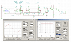
Went with a servo instead, as shown below. Some other values have been changed to improve headroom, and a second voltage reference was added. 47uF bypass caps at the voltage references. Although the servo settling time isn't good in conjunction with the coupling cap, I'm interested to see how the wobble interacts with compression given the asymmetrical nature of the amp. Nevertheless, frequency response is very flat down to 10Hz.
Parts have just arrived and the scope is ready, so I should have some results tonight or tomorrow.
First thought was a differential follower, but I don't know how to make one that can handle 6 to 10Vpp at the input without excessive emitter degeneration. Second thought was eliminating the output transformer altogether, but the Octa-Capture is transformerless and I don't know how the signal would be affected in the presence of multiple floating supplies without electrical isolation.
Went with a servo instead, as shown below. Some other values have been changed to improve headroom, and a second voltage reference was added. 47uF bypass caps at the voltage references. Although the servo settling time isn't good in conjunction with the coupling cap, I'm interested to see how the wobble interacts with compression given the asymmetrical nature of the amp. Nevertheless, frequency response is very flat down to 10Hz.
Parts have just arrived and the scope is ready, so I should have some results tonight or tomorrow.
Attachments

Last edited:
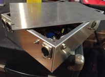
It's finished. The final build separated the power supply into its own enclosure next to the main board for safety, and the preamp circuits were modified a fair bit as well. From a usability standpoint, it's absolutely terrible, yet I stand by the concept of a configurable preamp. Sound is fair to good, noise is so-so. Hopefully in a year or so I'll be able to try again with more time.
Thanks again; I learned a lot doing this.
Thanks again; I learned a lot doing this.
Attachments
- Status
- This old topic is closed. If you want to reopen this topic, contact a moderator using the "Report Post" button.
- Home
- Source & Line
- Analog Line Level
- Preamp Design - Novel or Silly?