Seeing the Lightspeed's name has been bought into it a few times now, this need to be said.
This thread is going around in circles and this needs to be said about forced matching, auto calibration, or feedback type circuits, as there are now a few clones doing this around the world, to get out of doing the hard yards and hand quad matching the led/ldr's.
Any form of active auto matching (forced matching, feedback) circuit/s for the LED/LDR's makes the Lightspeed an "active preamp" as these circuits are attached to the output signal, and must be recalibrated every time the volume is touched. As well with forced matching, one or some LED/LDR's can get "over powered" to stay matched with the others, and therefore will have minimal life expectancy.
I've tried with help of very good designers various different ways of doing this type of "forced matching" and all were detrimental to the sound quality because of the active circuitry attached to the output signal to monitor the LDR's impedances. Compared to doing it the hard way with just matched quad sets and "no" forced matching circuits, keeping the Lightspeed totally passive from input to output keep the source signal pure.
http://www.diyaudio.com/forums/anal...uator-new-passive-preamp-193.html#post2404681
http://www.diyaudio.com/forums/anal...uator-new-passive-preamp-193.html#post2404872
Cheers George
Last edited:
I recently constructed an LDR attenuator and volume control from Tortuga Audio. I was rather surprised and very impressed once I connected this up in my music system...
The same just happened to me. I thought that LDRs cannot make such a difference, but I wanted to give it a try and hear. Once I had an LDR attenuator I was quickly convinced that LDRs are better than pots, if implemented well.
At first I also wanted to use the Tortuga unit, but, at the time, it was a bit hard to fully understand all the details of the design and how it's requirements would fit in my environment (PSU, control device, etc.). To make life easy, I tried the OptiVol, which is certainly not the most accurate unit out there -- but it's cheap and easy. And it really got me hooked to the LDR sound! Getting rid of that mechanical wiper in the signal path really seems to be a good thing. But the OptiVol only has a limited attenuation range and channel imbalance is rather poor.
Then I found the precisionLDR (BTFSystems by wapo54001 here on diyAudio; see here, here, and here). I really like this design -- it's easy to implement in an existing system and it's very accurate. I measured attenuation to be very linear, and channel imbalance (0.5 dB typical) is better than with many high quality pots.
And there's one more thing I like about the LDR approach: since the audio signal does not "pass the control knob", the knob does not have to be where the audio signal is. For instance, the knob can be where you listen to music, while the LDR attenuator itself is installed close to the amplifiers, which may sit near the speakers for a nice and short signal path. Just use a cable long enough to connect the control knob to the LDR board.
You should also look at this design :
http://www.diyaudio.com/forums/anal...d-ldr-volume-source-selection-controller.html
totally passive from input to output keep the source signal pure.
what marvellous marketing weasel words.
You've been told here by AndrewT he tried to explain it to you as well Bill, I'm not going to go through it as well
There no need for a buffer if I/O impedances are in order The fact is if all is correct an active buffer (no matter how transparent, which none are) can only be detrimental to the sound of the source, even if it's bad sound.
http://www.diyaudio.com/forums/pass-labs/262973-double-buffered-b1.html
Cheers George
Seeing the Lightspeed's name has been bought into it a few times now, this need to be said.
This thread is going around in circles and this needs to be said about forced matching, auto calibration, or feedback type circuits, as there are now a few clones doing this around the world, to get out of doing the hard yards and hand quad matching the led/ldr's.
Any form of active auto matching (forced matching, feedback) circuit/s for the LED/LDR's makes the Lightspeed an "active preamp" as these circuits are attached to the output signal, and must be recalibrated every time the volume is touched. As well with forced matching, one or some LED/LDR's can get "over powered" to stay matched with the others, and therefore will have minimal life expectancy.
Cheers George
Wait, WHAT??!! George, no. During calibration using my circuit, the LDRs are disconnected from the input/output circuit and the LDR is calibrated in isolation. After the 12-minute calibration cycle -- which has been found to hold accuracy for very long periods (a year, so far) -- the calibration circuit is entirely disconnected from the LDRs which are reconnected to the input and output circuit and the memorized current values are then used to achieve a given LDR resistance and maintained with absolutely no connection or feedback from the resistive elements of the LDR. The LDR is not recalibrated each time the volume control is touched, absolutely not!
At no time is the operational circuit and the calibration circuit connected and working simultaneously. During operation, LED current is delivered exclusively based on a value stored in a table in the microprocessor to achieve a certain resistance, and no feedback is involved, the current is delivered based strictly on memorized values which are related only to the position of the volume control.
Control of course is applied to the current flowing through the LED in order to keep it constant. So why is that bad? And once stabilized at a volume setting, the control signals are so small that they are barely visible at the most sensitve setting of a top-drawer oscilloscope and they happen very intermittently in the diode circuit. There is never any feedback from the resistive element of the audio circuit during operation, never.
And "Over Powered"??? No LDR in my circuit EVER sees more than 10 milliamps, ever, from fully muted to maximum volume, period. That current is limited by precise microprocessor control. The Lightspeed cannot claim the same, with the only current limiter being a 120 ohm resistor. With voltage from a 5.0V regulator and a 2.0V LED, that 120 ohms has to drop 3.0 volts, and your current is limited to a maximum of 25 milliamps which in my humble opinion, is too much current. Which is more harmful to the LDR -- your 25 milliamps or my 10 milliamps (considering the published maximum current figure for the NSL32-SR2s is 20 milliamps)? Hmm?
George, my device can precisely emulate a smoothly curving 10K logarithmic attenuator which has better than 1dB channel-to-channel tracking across the entire attenuation curve. And I do it with a maximum of 10 milliamps per LDR which virtually guarantees long-term healthy operation. My system is nothing like the way you describe it. I don't misrepresent your design; stop misrepresenting mine.
If anyone doubts that the LDRs are not connected to calibration circuits during operation of a microprocessor-based LDR attenuator, please visit Instructions & Description - BTFSystems LLC and view the calibration instructions on the "Technical" tab. Very simple, very clear.
Last edited:
During calibration using my circuit, the LDRs are disconnected from the input/output circuit and the LDR is calibrated in isolation. After the 12-minute calibration cycle The LDR is not recalibrated each time the volume control is touched, absolutely not!
No LDR in my circuit EVER sees more than 10 milliamps, ever, from fully muted to maximum volume, period. .
Ok then if this is how your auto calibration works, if your saying there is no active element/s attached to the signal path while listening.
I still have a question on the max being only 10ma for the led section of the shunt ldr, as this then will not give a very low minimum volume, especially with todays louder recordings, as the shunt ldr will not get low enough needed for low level listening, and with efficient speakers and an amps that has high input sensitivity (1v or .5v for max output, volume will be too loud at minimum volume.
Cheers George
I note you include all control types in the first. But in this second you exclude "auto calibration"..............this needs to be said about forced matching, auto calibration, or feedback type circuits,..................
so I assume you mean that all these types of control are bad in comparison to the "original" Lightspeed?...................Any form of active auto matching (forced matching, feedback) circuit/s for the LED/LDR's makes the Lightspeed an "active preamp" as these circuits are attached to the output signal, and must be recalibrated every time the volume is touched. As well with forced matching, one or some LED/LDR's can get "over powered" to stay matched with the others,
This seems to be a completely unfounded claimand therefore will have minimal life expectancy.
another claim that cannot be justified in the light of evidence provided on this Forum.I've tried with help of very good designers various different ways of doing this type of "forced matching" and all were detrimental to the sound quality because of the active circuitry attached to the output signal to monitor the LDR's impedances. Compared to doing it the hard way with just matched quad sets and "no" forced matching circuits, keeping the Lightspeed totally passive from input to output keep the source signal pure.
I kept quiet when I saw George's first correcting of "facts" repost and assumed George was aware of Wapo's control and had excluded it from his critcal comments.Ok then if this is how your auto calibration works, if your saying there is no active element/s attached to the signal path while listening.
It now appears that George was unaware of the Wapo style of control and was intending that it too should be lumped into the "bad" LED/LDR types.
And having heard from the Designer he still does not believe
Wapo knows how he designed the control of the output.if this is how your auto calibration works, if your saying there is no active element/s attached to the signal path while listening.
This applies to all the LED/LDR volume attenuators that have a lower limit of around 20ohms to 40ohms.I still have a question on the max being only 10ma for the led section of the shunt ldr, as this then will not give a very low minimum volume, especially with todays louder recordings, as the shunt ldr will not get low enough needed for low level listening, and with efficient speakers and an amps that has high input sensitivity (1v or .5v for max output, volume will be too loud at minimum volume.
Adequate attenuation from a 10k vol pot requires 1ohms (-80dB) to 10ohms (-60dB) as the minimum lower leg resistance value.
But many here can work with -40dB to -50dB of maximum attenuation and here the LED/LDR works admirably, since this requires a lower leg value of around 30ohms to 100ohms. Well within, or just about within, the "safe" maximum long term current of the LED side of the control.
Last edited:
You've been told here by AndrewT he tried to explain it to you as well Bill, I'm not going to go through it as well
There no need for a buffer if I/O impedances are in order The fact is if all is correct an active buffer (no matter how transparent, which none are) can only be detrimental to the sound of the source, even if it's bad sound.
http://www.diyaudio.com/forums/pass-labs/262973-double-buffered-b1.html
Cheers George
Nice try, but completely out of context. Andrew was saying I didn't need a buffer BEFORE the pot. In many cases he is right. We are in perfect agreement that a transparent buffer after the volume control is a good thing. But you have beliefs to enforce to help your pitch.
Ok then if this is how your auto calibration works, if your saying there is no active element/s attached to the signal path while listening.
I still have a question on the max being only 10ma for the led section of the shunt ldr, as this then will not give a very low minimum volume, especially with todays louder recordings, as the shunt ldr will not get low enough needed for low level listening, and with efficient speakers and an amps that has high input sensitivity (1v or .5v for max output, volume will be too loud at minimum volume.
Cheers George
That is precisely what I'm saying -- there is no active element/s attached to the signal path while listening.
My system uses memorized current drive values delivered with extreme precision always at values below 10 milliamps. And when I say "10K pot" it's a 10K pot with low end resistance within one or two ohms of 40 ohms and the upper 10K level typically accurate to maybe +/- 300 ohms.
I have always been totally transparent on this score -- it is a 10K pot, and because the shunt LDR is limited to precisely 40 ohms under microprocessor control, the attenuation range is always from almost zero dB to -48.5dB, plus full mute (inaudible). This is accomplished with no more than 10 milliamps per LDR, ever, and can be closer to 5 milliamps depending on the individual LDRs used.
Folks who are using my device have said that this 48dB range is more than adequate and at low volume the sound level is very low. If there is an unusual system out there with very high sensitivity, -48dB may not be enough attenuation, but a) I haven't encountered it yet and b) that would be an unfortunate situation where the user's volume control would sit in the very lowest range all of the time regardless of which attenuator is used -- and that's not ideal for any control system.
For most users, -48.5dB is totally adequate, and with my board it's delivered with great precision, always at less than 10 milliamps per LDR. Much higher attenuation at less than 10 milliamps is possible - 60dB plus -- by going to a larger value pot, say 25K or 50K, but that would not be a good impedance match for solid-state amplifiers with 25K inputs. so my pot is 10K which is a good match for such amplifiers.
wow, poor OP.
Life... we are born, we live our life and we die. its what happens in between when we are living out life that determines the quality of it. if small luxury's make us happy then is it not worth it. lets take ice cream as an example, i like some of the locally made ice cream in the area i stay but others dont and prefer another locally made one. both ice creams are made from the same basic ingredients its just made different at different ice cream makers. to me ice cream is a treat so its a luxury and as such makes my life better. i'm not very good at making ice cream so i leave that up to the experts.
i suppose what i'm trying to say is if the OP is happy with his purchase and hears a difference should that not qualify as a luxury in life just like ice cream. now that he is happy he wants to share his happiness with others to encourage them to try this new ice cream he has found, its up to others to decide for themselves if they want to or not.
i know there are a lot of electronics experts on this forum but there are also other experts that disagree from time to time on how things are done, i suppose if you put a bunch of ice cream makers together you would get the same thing, they are all making the same thing from the same ingredients but just mixing them different for the same end result and that end result is what makes the difference that individuals like. if we all liked the same technically perfect ice cream made by one manufacturer then life would be very boring indeed.
Sorry wapo54001, but are you saying that with a maximum of 10mA drive to the led side, you can get the ldr component side to come down to 40ohm on the same NSL?
Cheers George
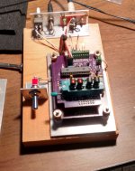
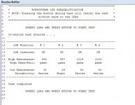
Absolutely, all my shunt LDRs achieve 40 ohms with less than 10 milliamps of current. Many achieve 40 ohms with much less current -- one in the image will go to a very low resistance at 10 milliamps which means in practise it takes far less than 10 milliamps to achieve 40 ohms.
Take a look at my automated LDR prequalification station and display. I can define the important parameters for four LDRs at a time and the test takes about 30 seconds.
The test is pass/fail for high resistance capability, and specifies the resistance achieved at 10 milliamps of drive and specifies the recommended application for each specific LDR. It's a piece of cake to separate shunt-capable LDRs from series-capable LDRs, and to entirely weed out the occasional dud which does not meet basic requirements.
The reason one of the red-dot LDRs is qualified as a series instead of a shunt in the image is that I recently changed the qualification criterion for shunt from 40 ohms at 10 milliamps to 39 ohms, and the LDR was identified under the old system but no longer passes the shunt test under the new criterion.
Interestingly, the reason for the change was that I was getting too many LDRs qualifying for shunt duty!
Attachments
Last edited:
I won't argue with what you've presented.
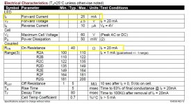
But from my experience I've found that 20mA of led current is needed (without pushing to the 25mA safe max rating), to get the brightness need to make the shunt ldr get down to 40ohms for low level listening or background music in a medium to high efficiency system. And the specs of the NSL32SR2S confirms this also.
Cheers George
Attachments
Last edited:
I won't argue with what you've presented.
But from my experience I've found that 20mA of led current is needed (without pushing to the 25mA safe max rating), to get the brightness need to make the shunt ldr get down to 40ohms for low level listening or background music. And the specs of the NSL32SR2S confirms this also.
Cheers George
You do recognize that those figures are guaranteed minimum specifications? And you did hear me say that I separate shunt-capable and series-capable LDRs? So I cherry-pick for shunt LDRs. I can do that because I've developed a system that makes it very easy to do, and more than half of my tested units meet that criteria, and the other half do not.
So, if you don't do any sorting, then you do have to plan on driving LDRs to 20 milliamps to get 40 ohms. But if you do sort as I do, then you can make that happen with just 10 milliamps and all of a sudden you have LDRs in your system that just loaf along at less than half power and therefore stay in calibration almost indefinitely.
I can see that sorting would be very difficult or impossible for a Lightspeed type circuit because matching the resistance curve takes precedence over current at 40 ohms. In the case of my circuit however, practically any LDR can be made to precisely match practically any other LDR, so now sorting primarily by resistance at 10 milliamps becomes feasible.
This is one of the great advantages of how I make LDRs work in my systems. My design is to the point where you can just about treat LDRs as you would any other component -- it's not going to fail early, it's not going to go out of calibration, it's mostly a commodity now rather than an esoteric component that requires frequent fiddling. And size can be kept very small -- about 2.5 inches by 3 inches -- so it'll fit in many difficult locations.
Yes your system does take the matching of the LDR's out of the equation, as I have to do at 5 different mA points for all 4 NSL32RS2S's.
But I will still say there is no way with only 10mA of led current it can get low enough in volume. Which will make it too loud for low level listening especially in med to high efficiency systems.
I get 35-40ohm with 20mA which is just low enough for low level listening in med to high efficiency systems. If I were to take them to the max safe of 25mA I could get 20 -35ohms, but I don't push them that hard even though the data sheet says it's safe .
Cheers George
Interesting. I know with Vincent's system he uses 7ma max I think. I just tried it on minimum setting of 1 (0f 50) and I can barely hear it. There is also a mute relay which kicks in at 0 to make it completely silent. He does up the series resistance to achieve more attenuation though. At a setting of 1 the shunt is about 200ohm, the series about 1Mohm. For led longevity surely the lower the maximum current the better?
See : http://www.diyaudio.com/forums/anal...d-ldr-volume-source-selection-controller.html
See : http://www.diyaudio.com/forums/anal...d-ldr-volume-source-selection-controller.html
Interesting. I know with Vincent's system he uses 7ma max I think. I just tried it on minimum setting of 1 (0f 50) and I can barely hear it. There is also a mute relay which kicks in at 0 to make it completely silent. He does up the series resistance to achieve more attenuation though. At a setting of 1 the shunt is about 200ohm, the series about 1Mohm. For led longevity surely the lower the maximum current the better?
See : http://www.diyaudio.com/forums/anal...d-ldr-volume-source-selection-controller.html
I think below a reasonable level it doesn't much matter how low the maximum current goes. I'm comfortable with 10 milliamps.
At typical listening levels (20~70 on my readout scale of 1~99) my LDR current readout shows less than 2ma at the low end of that and less than 0.1ma at any value above 50. So, maximum current doesn't apply unless you are constantly listening with the volume turned very low. In mute, my system draws 2.5 milliamps per shunt LDR.
I suppose a 1 megaohm LDR pot has the same input Z and output Z issues as a 1 megaohm conventional pot. I don't think that would play well with a typical solid-state amplifier with an input Z of 25K to 50K ohms. I've done the impedance curves for a 10K pot. For a 10K, the maximum output Z occurs at about -12dB, and it's 2500 ohms. If the same math applies to Vincent's 1 megaohm pot, the maximum output Z of the pot would be 250K ohms -- definitely not a good value to put in front of a 25K input impedance solid-state amplifier. That would be a serious impedance mismatch.
Hi Wapo, I think Vincent only uses high series resistance at very high attenuation. At normal listening levels it emulates a 10k pot though it can also be set in software to emulate up to 50k as well I think.
- Home
- Source & Line
- Analog Line Level
- LDR Attenuator Impressions