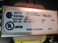
I would really like to get this preamp working but have had no luck thus far. It came to me with the transformer & LC7818 IC already replaced. I do not have a schematic so I have been guessing.
I have replaced:
LC7818 (again)
LC4966
4001BE
(1 of 2) LM833N op-amp
2N5087 transistors
what's left:
(1) LM833N
(2) AD712JN op-amp
I've been using dbt for power ups. When I kill the power on the dbt I hear music for a brief moment but that is it. Function switch does nothing.
Should I bother changing the op amps or is this unit a lost cause?
I've got the voltages. I should note that with the function switch in "OFF" and dbt on I can get the same voltages and operate the mute switch turning the light on.
LM833N (Near function switch)
1 out A: (+-) 13.76v
2 - IN A: 0
3 +IN A: erratic(+-)
4 -Vee: -1520v
8 +Vcc: +15.20v
7 out B: (+-) 13.25v
6 -IN B: (+-) 22mv
5 +IN B: erratic (+-)
(+-) meaning alternating (+-) readings every second or 2.
LM833N (near headphone jack)
1 out A: +11mv
2 - IN A: +11mv
3 +IN A: +10mv
4 -Vee: -15.20v
8 +Vcc: +15.13v
7 out B: +11mv
6 -IN B: +11mv
5 +IN B: +10mv
AD712 (both ICs)
1 output: 0mv
2 Inverting input: 0mv
3 non-inverting input: 0mv
4 V-: -15.20v
8 V+: +15.10v
7 output: +1mv
6 inverting Input: 0mv
5 Non-inverting Input: 0mv
LC4966
1 in/out: +10mv
2 In/out: -45mv
3 In/out: -43mv
4 in/out: 0mv
5 CONTB: -15.20v
6 CONTC: -15.20v
7 Vss: -15.20v
14 Vdd: +15.13v
13 CONTA: -15.20v
12 CONTD: -15.20v
11 In/out: 0mv
10 in/out: -50mv
9 in/out: -47mv
8 in/out: +10mv
Your supplies are good. The first LM833 appears to have a problem with the outputs varying.
Has this unit any hidden history ? such as it being an ebay purchase")
I would tend to suspect something physical at this stage such as broken or cracked print, rather than a purely electronic problem.
Has this unit any hidden history ? such as it being an ebay purchase
I would tend to suspect something physical at this stage such as broken or cracked print, rather than a purely electronic problem.
I don't know about ebay history. I picked it up from a fellow audiophile, he said it was sold to him working but never did since he had it. He paid someone to install the transformer and LC7818. I will try to find a broken print or cracked solder joint. I have already changed that first LM833.
here's a few pics. I'm told the diodes (near LC7818) are factory and were not added by the last tech. I have seen other pics of these cs-117 units that have through hole pcb spots for these diodes. For whatever reason this one does not.
here's a few pics. I'm told the diodes (near LC7818) are factory and were not added by the last tech. I have seen other pics of these cs-117 units that have through hole pcb spots for these diodes. For whatever reason this one does not.
Attachments
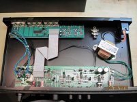
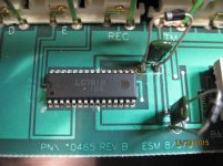
Things like the diodes are the kind of 'in production' modifications that manufacturers often add to production runs to correct some problem that comes to light.
OK, so the unit has history... its been passed along and passed off as working when it clearly doesn't. Without a circuit you are going to have to try and visualise the circuit configuration. In the first instance you need to determine whether that first op-amp is configured as inverting or non inverting. I still suspect damaged print or some such for this. Look closely around the switch...any parts that stick out are favourite for taking a knock and causing damage.
OK, so the unit has history... its been passed along and passed off as working when it clearly doesn't. Without a circuit you are going to have to try and visualise the circuit configuration. In the first instance you need to determine whether that first op-amp is configured as inverting or non inverting. I still suspect damaged print or some such for this. Look closely around the switch...any parts that stick out are favourite for taking a knock and causing damage.
I couldn't find any broken traces or solder joints. I did re-solder and deoxit the function switch. I replaced the IC socket and swapped out both LM833n op-amps since I have them but no results. I still haven't figured out if the LM833 is inverting or non-inverting. without a schematic this is really tuff, and im just a novice.
With the supply voltages good does that mean the ICs and op-amps are good?
With the supply voltages good does that mean the ICs and op-amps are good?
Not having a circuit makes this difficult but one thought having looked at the pictures is that the left hand opamp looks like it could possibly be a 'phono amp' for records. If you apply shorting plugs to the sockets that the green and blue wires go to, do the voltages on that opamp stabilise ?
With the supply voltages good does that mean the ICs and op-amps are good?
Not necessarily, however op-amps like most IC's are extremely reliable and it would be unlikely for them to have a problem.
You really need to try and get a circuit diagram for this if possible.
With the supply voltages good does that mean the ICs and op-amps are good?
Not necessarily, however op-amps like most IC's are extremely reliable and it would be unlikely for them to have a problem.
You really need to try and get a circuit diagram for this if possible.
thank you for your help mooly I will try that later. It does look like a phono section. This amp shares phono/AUX on the same slot in the function switch. In order to choose if you want phono there's supposed to be a switch inside to choose witch function of the two. This unit does not have any switch so I have no idea what's up with that. I will try my luck posting looking for a schematic.
- Status
- This old topic is closed. If you want to reopen this topic, contact a moderator using the "Report Post" button.
- Home
- Source & Line
- Analog Line Level
- B&K CS-117 Preamp HELP!