The big tpa3116 thread over in the Class D sub-forum caused me to build more little amps than I care to admit. On about half of them I put a simple potentiometer or stepped attenuator volume control. I figured I'll build more amps as time goes on (though not necessarily tpa3116-based), and it might be more efficient in terms of time to have a separate component for volume control, so I don't have to keep implementing this feature.
I did a little searching and found inspiration in the Emotiva Control Freak and (at 10x the price) the Goldpoint SA1X. I really wanted to get the Goldpoint, but the price put it out of my reach.
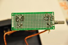
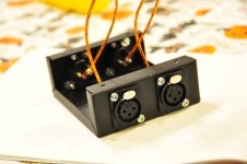
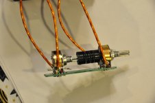
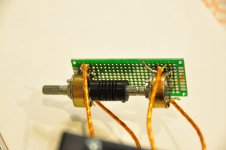
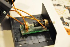
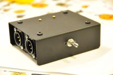
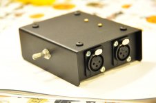
So I implemented my own "poor man's SA1X" using these "DACT Type 21" stepped attenuators on ebay. In particular, you can get a balanced (XLR) "double" attenuator for about $40 USD. I had one gender of XLR jacks on hand, bought the other gender; I also bought a cheap steel case. I already had the hook-up wire, and I bought some 0-ohm SMT resistors to attempt to make my PCB work half-way decent-looking.
In a move that may prove silly, I then thought I could somewhat ruggedize this device by potting it with hot melt glue. Time will tell if I come to regret this.
So far, I've only briefly tested that it works (it does). This is actually the second one I built; one of the stepped attenuators in my first build went bad and basically turned into a short. That kind of wrecked my confidence with these things, but I'm hoping it was just a one-time fluke.
Anyway, just thought I'd post it here, because someone else might find some inspiration in the idea; it's a simple build. Enjoy the pics!
I did a little searching and found inspiration in the Emotiva Control Freak and (at 10x the price) the Goldpoint SA1X. I really wanted to get the Goldpoint, but the price put it out of my reach.
So I implemented my own "poor man's SA1X" using these "DACT Type 21" stepped attenuators on ebay. In particular, you can get a balanced (XLR) "double" attenuator for about $40 USD. I had one gender of XLR jacks on hand, bought the other gender; I also bought a cheap steel case. I already had the hook-up wire, and I bought some 0-ohm SMT resistors to attempt to make my PCB work half-way decent-looking.
In a move that may prove silly, I then thought I could somewhat ruggedize this device by potting it with hot melt glue. Time will tell if I come to regret this.
So far, I've only briefly tested that it works (it does). This is actually the second one I built; one of the stepped attenuators in my first build went bad and basically turned into a short. That kind of wrecked my confidence with these things, but I'm hoping it was just a one-time fluke.
Anyway, just thought I'd post it here, because someone else might find some inspiration in the idea; it's a simple build. Enjoy the pics!
Attachments
-
 DSC_9349-scaled40.jpg159.9 KB · Views: 319
 -
 DSC_9353-scaled40.jpg753.3 KB · Views: 299
 -
 DSC_9354-scaled40.jpg656 KB · Views: 285
 -
 DSC_9358-scaled40.jpg125.7 KB · Views: 280
 -
 DSC_9362-scaled40.jpg840 KB · Views: 283
 -
 DSC_9366-scaled40.jpg153.6 KB · Views: 174
 -
 DSC_9383-scaled40.jpg850.9 KB · Views: 161
 -
 DSC_9384-scaled40.jpg837.7 KB · Views: 107
How does you circuit arrange for the balanced impedance?
I'm not sure I understand the question, could you elaborate?
Thanks!
I see. This is simple enough that I think I can explain it verbally. If not, I'll try to draw a diagram and/or annotate one of my pics.
Consider a simple potentiometer or stepped-attenuator, it will have three pins:
- Input
- Output
- Ground
The stepped attenuator I used has twelve total pins. It's effectively a "4-in-1" or "quad" stepped attenuator, so it has:
- 4x input
- 4x output
- 4x ground
Due to using balanced/XLR connections, I have exactly four signal lines:
- left channel positive (L+)
- left channel negative (L-)
- right channel positive (R+)
- right channel negative (R-)
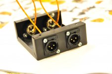
And in case it's not obvious, I have two each XLR male (L/R output) and female (L/R input) sockets:
- XLR_Female_1
- XLR_Female_2
- XLR_Male_1
- XLR_Male_2
So consider just one signal line, say R+:
All four together looks like this:
I jumpered the grounds for each pair of attenuators. So attenuators 1 and 2 have a common ground, and attenuators 3 and 4 share a ground. Thus:
Now that I typed all that out, a diagram probably would have been simpler.")
Let me know if it's still unclear!
Consider a simple potentiometer or stepped-attenuator, it will have three pins:
- Input
- Output
- Ground
The stepped attenuator I used has twelve total pins. It's effectively a "4-in-1" or "quad" stepped attenuator, so it has:
- 4x input
- 4x output
- 4x ground
Due to using balanced/XLR connections, I have exactly four signal lines:
- left channel positive (L+)
- left channel negative (L-)
- right channel positive (R+)
- right channel negative (R-)
And in case it's not obvious, I have two each XLR male (L/R output) and female (L/R input) sockets:
- XLR_Female_1
- XLR_Female_2
- XLR_Male_1
- XLR_Male_2
So consider just one signal line, say R+:
Code:
XLR_Female_1 pin_2 -> attenuator_1 input, attenuator_1 output -> XLR_Male_1 pin_2All four together looks like this:
Code:
XLR_Female_1 pin_2 -> attenuator_1 input, attenuator_1 output -> XLR_Male_1 pin_2
XLR_Female_1 pin_3 -> attenuator_2 input, attenuator_2 output -> XLR_Male_1 pin_3
XLR_Female_2 pin_2 -> attenuator_3 input, attenuator_3 output -> XLR_Male_2 pin_2
XLR_Female_2 pin_3 -> attenuator_4 input, attenuator_4 output -> XLR_Male_2 pin_3
I jumpered the grounds for each pair of attenuators. So attenuators 1 and 2 have a common ground, and attenuators 3 and 4 share a ground. Thus:
Code:
XLR_Female_1 pin_1 -> attenuator_1+2 gnd, attenuator_1+2 gnd -> XLR_Male_1 pin_1
XLR_Female_2 pin_1 -> attenuator_3+4 gnd, attenuator_3+4 gnd -> XLR_Male_2 pin_1
Now that I typed all that out, a diagram probably would have been simpler.
Let me know if it's still unclear!
Clearly I don't understand what a balanced impedance connection is.That's clear enough to recognise you don't have a balanced impedance connection.
You are wasting your time.
How is this different than putting a stereo pot (with single ended inputs) in between a source and amp for volume control?
Unbalanced interconnections do not require balanced impedance connections, neither from the Source, nor at the Receiver.
Balanced impedance interconnections DEMAND balanced impedance from the Source and at the Receiver.
Your vol pots can never achive the balance required of a balanced impedance connection.
Read up on balanced impedance
D.Self, Jensen, Whitlock, ESP, B.Putzeys and many others.
Balanced impedance interconnections DEMAND balanced impedance from the Source and at the Receiver.
Your vol pots can never achive the balance required of a balanced impedance connection.
Read up on balanced impedance
D.Self, Jensen, Whitlock, ESP, B.Putzeys and many others.
Signal connections are OK IMO, only XLR pin 1 has no business connecting to the "grounds" (which actually aren't and must remain floating and independent). Pin 1 must go directly to case everywhere, so the cable shield and cases of connected devices form an enclosed Faraday cage.
Last edited:
- Status
- This old topic is closed. If you want to reopen this topic, contact a moderator using the "Report Post" button.
- Home
- Source & Line
- Analog Line Level
- Passive Pre XLR Volume Control (Poor Man's Goldpoint SA1X)