Soooo...
I figured I eventually would have to do this...so here is what I threw together based on what I read in the thread about testing these jfets. Unfortunately I don't have a bread board, and Ratshack wasn't open yet to try and get one.
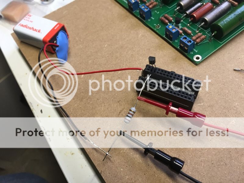
I rang out the pin sockets on this unused jumper cable I had from my miniDSP kit to make sure I knew where I had continuity.
There is a small bridge soldered to the end of a 100 Ohm resistor which plugs into the corresponding sockets for the gate and source when the jfet is plugged in.
So gate and source are joined.
The positive post on the 9 volt battery is fed to the drain.
There other end of the 100 Ohm resistor is connected to the negative post on the battery.
The battery itself gave me about 9.4 volts with my DMM.
I am measuring DC voltage across the resistor.
At first I thought I screwed up (maybe I did). I wasn't getting a reading. I tried another new GR jfet in the socket and the meter jumped for a second. I tried some light pressure on the jfet in the socket and it gave me a reading that settled down pretty well with slow fluctuation.
Evidently the sockets are a little loose for the legs of the jfets, so they need to be held lightly in place.
The reading I got on the new unused jfet was .437 volts. Which according to Mr Pass' guidance on the subject "1 volt=10mA", means I have an Idss of 4.37 mA?
The other jfet that I had already attempted soldering in as a replacement measured about .443 I believe, which puts it at 4.43 mA if I'm doing this correctly.
If I'm doing this correctly the two were just beyond the 1% matching as advertised by the seller.
My question is am I doing this correctly? Does this prove the jfets are in good operating condition?
Kevin
I figured I eventually would have to do this...so here is what I threw together based on what I read in the thread about testing these jfets. Unfortunately I don't have a bread board, and Ratshack wasn't open yet to try and get one.
I rang out the pin sockets on this unused jumper cable I had from my miniDSP kit to make sure I knew where I had continuity.
There is a small bridge soldered to the end of a 100 Ohm resistor which plugs into the corresponding sockets for the gate and source when the jfet is plugged in.
So gate and source are joined.
The positive post on the 9 volt battery is fed to the drain.
There other end of the 100 Ohm resistor is connected to the negative post on the battery.
The battery itself gave me about 9.4 volts with my DMM.
I am measuring DC voltage across the resistor.
At first I thought I screwed up (maybe I did). I wasn't getting a reading. I tried another new GR jfet in the socket and the meter jumped for a second. I tried some light pressure on the jfet in the socket and it gave me a reading that settled down pretty well with slow fluctuation.
Evidently the sockets are a little loose for the legs of the jfets, so they need to be held lightly in place.
The reading I got on the new unused jfet was .437 volts. Which according to Mr Pass' guidance on the subject "1 volt=10mA", means I have an Idss of 4.37 mA?
The other jfet that I had already attempted soldering in as a replacement measured about .443 I believe, which puts it at 4.43 mA if I'm doing this correctly.
If I'm doing this correctly the two were just beyond the 1% matching as advertised by the seller.
My question is am I doing this correctly? Does this prove the jfets are in good operating condition?
Kevin
Yes. And around 4mA is expected for a GR grade Jfet. The matching tolerance can vary if matched at a different voltage or as an average of different voltages or even temperature. I think you are fine with the match.
Still think you have a bad solder joint somewhere and would love to see a pic of the underside of the board. Here's a photo I stole from the internet. You can see how the ground plane on the underside of the boards is "cut out" from the solder pads. If you accidentally create a solder bridge with a blob of solder that is too large between a solder pad and that plane bad things will happen.
Still think you have a bad solder joint somewhere and would love to see a pic of the underside of the board. Here's a photo I stole from the internet. You can see how the ground plane on the underside of the boards is "cut out" from the solder pads. If you accidentally create a solder bridge with a blob of solder that is too large between a solder pad and that plane bad things will happen.
Attachments
Well it's been educational...However, I wish my results from testing the jfets were better.
One of the quads I bought seemed fine, and matched very closely.
However the quad I had borrowed a Jfet from to try in the phono amp was not as it should have been.
I was very consistent and methodical in the testing. I even used a timer to allow each Jfet to stabilize for the same amount of time of about a minute.
Of course I don't have a temperature controlled room or a high tech power supply, but all the jfets were at the same ambient temperature, tested for the same length of time and there was only 8 in total.
There was no drain measureable on the 9 volt battery as compared before and after testing.
Still, one Jfet of that quad was out by over 20%. I retested the set three times and got the same results each time.
I guess I'll have to contact the seller and see if they are willing to supply replacements.
I wanted to use a pair of jfets from the set to replace the Jfet at Q1 I damaged while removing it and Q1 in the other channel so that they were matched properly, but I may have to wait to see what the seller says they wants to do. As it is I already mounted one out of the set...I hope that doesn't come back and bite me as I wanted the additional pair for a MC stage if I need one.
I tested the resistors that are isolated now without Q1 mounted in the bad channel and they measured fine...I went on to retest all the resistiors on the board again and did get strange measurements on the input and output load resistors from one channel to the other.
For some reason the load resistor on the good channel at R2 didn't measure 47.5k...perhaps because it's in circuit? It's value was creeping slowly upwards. R2 in the bad channel did measure properly.
I had the reverse happen with R13. The good channel with all components mounted measured properly. The bad channel missing the Jfet measured about .5 MOhms. I want to reinstall the missing Jfet and then see if the values match between channels. Unless it seems obvious to anyone that something is wrong there.
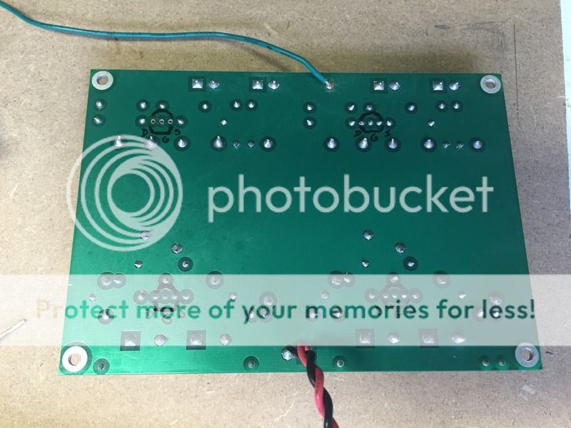
I'll post up a picture of the bottom of the board shortly. I did find a piece if solder debris stuck to the bottom near a soldering point when I was rechecking grounding and taking a picture. I'm not sure if it was there due to handling during tests or if it could have been the source of the problem.
Here's a pic...
One of the quads I bought seemed fine, and matched very closely.
However the quad I had borrowed a Jfet from to try in the phono amp was not as it should have been.
I was very consistent and methodical in the testing. I even used a timer to allow each Jfet to stabilize for the same amount of time of about a minute.
Of course I don't have a temperature controlled room or a high tech power supply, but all the jfets were at the same ambient temperature, tested for the same length of time and there was only 8 in total.
There was no drain measureable on the 9 volt battery as compared before and after testing.
Still, one Jfet of that quad was out by over 20%. I retested the set three times and got the same results each time.
I guess I'll have to contact the seller and see if they are willing to supply replacements.
I wanted to use a pair of jfets from the set to replace the Jfet at Q1 I damaged while removing it and Q1 in the other channel so that they were matched properly, but I may have to wait to see what the seller says they wants to do. As it is I already mounted one out of the set...I hope that doesn't come back and bite me as I wanted the additional pair for a MC stage if I need one.
I tested the resistors that are isolated now without Q1 mounted in the bad channel and they measured fine...I went on to retest all the resistiors on the board again and did get strange measurements on the input and output load resistors from one channel to the other.
For some reason the load resistor on the good channel at R2 didn't measure 47.5k...perhaps because it's in circuit? It's value was creeping slowly upwards. R2 in the bad channel did measure properly.
I had the reverse happen with R13. The good channel with all components mounted measured properly. The bad channel missing the Jfet measured about .5 MOhms. I want to reinstall the missing Jfet and then see if the values match between channels. Unless it seems obvious to anyone that something is wrong there.
I'll post up a picture of the bottom of the board shortly. I did find a piece if solder debris stuck to the bottom near a soldering point when I was rechecking grounding and taking a picture. I'm not sure if it was there due to handling during tests or if it could have been the source of the problem.
Here's a pic...
Last edited:
All the resistor values sound normal. The solder joints look good, just make sure none of them are bridging to the ground plane. You can test w/a meter if you can't tell by looking but they all look good from here.
I am out of ideas. Your jet mismatch would not cause this sound and high DC offset. The matching is just so both channels are the same. I am out of ideas.
I am out of ideas. Your jet mismatch would not cause this sound and high DC offset. The matching is just so both channels are the same. I am out of ideas.
Ring-A-Ding!!!


Got it working late last night.
Had a nice listening session this morning and it sounds great in my system.
Plenty of gain for my MM. I think I can try a passive pre or buffer...which I am happy about.
It may even possibly be enough with my MC step up to use a low output MC and a passive/buffer.
It appears that even though my solder joints looked good, and I reworked them on the jfets more than once, that I was getting an inferior joint.
This may have been due to the solder I am using (it was my fathers and had some oxidation on the surface) I didn't really think solder could go bad, especially rosen core, but I was coating the pads and component legs with some liquid flux to help purify the solder and get it to flow better.
I was also paranoid about cooking the jfets. I had to really heat the legs on both sides of the board to get a good joint and get the DC readings to stabilize. Almost like I was cooking the flux out of the joint.
I was only able to speculate this after I got my bad channel functioning and then went to put a matched jfet in the Q1 position of the other channel that had been working all along. After I installed the replacement jfet that channel was screwed up with the DC at the output all over the place just like the bad channel had been. I knew all I had changed was the jfet. So I kept reworking the joints on the legs until I saw the DC stabilize on the output. The same thing actually happen one more time on the channel I had been struggling to fix. I hit the joints once again and finally got it all stable and working properly.
Hard lesson learned. I can't be positive about it, but I'm ordering some decent new solder and I will be much more careful in the future about making sure that my solder joints don't just look good.
I took a lot away from this experience. Thank you all for your help and patience.
Regards
Kevin
I'm currently using a Clearaudio Virtuoso Rosewood. I had to repair it last year after a mishap resulted in a broken stylus. DIYAudio to the rescue! I found a thread that discussed how the styli are sourced from Audio-Technica. Had to do a little surgery, but had it up and running for less than $35 in about a week. Better than getting hosed by Clearaudio for a broken trade in and several hundred dollars!
It plays into the BHL phono amp and then directly into a miniDSP I put together from raw boards that I added a master volume control to.
I'm amplifying with a gainclone I built from a Peter Daniels premium kit.
It plays into a pair of Oris 200 horns I pieced together with a pair of Tang Band W8-1808 (all bought used on here).
The low frequencies are handled by an old Jamo SW 505E subwoofer that my wife's uncle gave me for free. This is more of a bandaid until I can build a proper bass solution...but it's not bad.
My miniDSP programming skills are minimal at this point. I simply set a first order slope at 150Hz.
I have a lot of ideas and experimenting I'd like to pursue. I'd like to take the miniDSP out of the chain and put a passive pre possibly buffered in its place and then just try using the subwoofer's on-board amp crossover.
For now, it's the first time in a while I have something that I feel has begun to really sing a bit. I was struggling with the equipment I had for a while.
Here's a fairly recent pic of the mess in my living room that my wife tolerates. It's right after I got my gainclone and miniDSP up and running. I need to do something about getting it reorganized properly.

Regards
Kevin
It plays into the BHL phono amp and then directly into a miniDSP I put together from raw boards that I added a master volume control to.
I'm amplifying with a gainclone I built from a Peter Daniels premium kit.
It plays into a pair of Oris 200 horns I pieced together with a pair of Tang Band W8-1808 (all bought used on here).
The low frequencies are handled by an old Jamo SW 505E subwoofer that my wife's uncle gave me for free. This is more of a bandaid until I can build a proper bass solution...but it's not bad.
My miniDSP programming skills are minimal at this point. I simply set a first order slope at 150Hz.
I have a lot of ideas and experimenting I'd like to pursue. I'd like to take the miniDSP out of the chain and put a passive pre possibly buffered in its place and then just try using the subwoofer's on-board amp crossover.
For now, it's the first time in a while I have something that I feel has begun to really sing a bit. I was struggling with the equipment I had for a while.
Here's a fairly recent pic of the mess in my living room that my wife tolerates. It's right after I got my gainclone and miniDSP up and running. I need to do something about getting it reorganized properly.
Regards
Kevin
Looks nice. Your cartridge should be happiest without any additional capacitance loading in the phono stage. One of the peculiarities of the booze hound is it has an above average amount of capacitance at the input of the stage...around 150pf I think. So no additional capacitance loading is desirable in your case. Once you add the phono cables and input at the stage you are probably at 250pf or so. So call it good.
Also, no buffer on the output of this thing. So, if you go passive a buffer is a good idea. I don't have experience with gainclones but the bhl phono in front of a 2050 tripath amp was not happy without a buffer between. I noticed bhl now has a hot rodded version with a buffer on output for sale too. The pass b1 buffer is nice...I had one of those yaqin tube buffers too.
I got the best results with cheap alkaline batteries from the dollar store. Nicads were smoother but had less impact. Also, the cap between the riaa stages (I think it's .1uf) and the output cap influence the sound a lot.
In the end alkalines and replacing the caps with with nice poly jantzen and REL caps got the sound I was after. Couldn't get it to sound good of an smps. Your preferences may be different. I moved on to the Salas phono which is kind of the ultimate le pacific style phono amp. It's better but the sound signature is similar. It's a great phono stage though...really an eye opener after using phono stages in integrated amps for years.
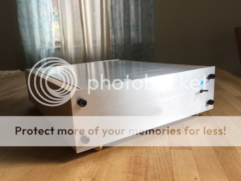
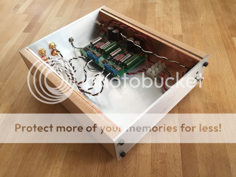
Where did you get that case? Pretty nice if its homemade.
Also, no buffer on the output of this thing. So, if you go passive a buffer is a good idea. I don't have experience with gainclones but the bhl phono in front of a 2050 tripath amp was not happy without a buffer between. I noticed bhl now has a hot rodded version with a buffer on output for sale too. The pass b1 buffer is nice...I had one of those yaqin tube buffers too.
I got the best results with cheap alkaline batteries from the dollar store. Nicads were smoother but had less impact. Also, the cap between the riaa stages (I think it's .1uf) and the output cap influence the sound a lot.
In the end alkalines and replacing the caps with with nice poly jantzen and REL caps got the sound I was after. Couldn't get it to sound good of an smps. Your preferences may be different. I moved on to the Salas phono which is kind of the ultimate le pacific style phono amp. It's better but the sound signature is similar. It's a great phono stage though...really an eye opener after using phono stages in integrated amps for years.
Where did you get that case? Pretty nice if its homemade.
Thanks...yes the case is home made. The fabrication aspect of these projects is what I enjoy the most. My background is in the arts and it allows me to feel creative.
I probably would have bought the new "Deluxe" version from BHL with the adjustable gain and buffer...but he started offering that after I ordered this one.
I have been considering the many different versions of the B1 buffer. It kind of makes sense to build a preamp around it instead of just a passive. I was considering trying to integrate it all into this case, that is why there's a bit of excess space. I just needed to simplify things and get it working like this first.
My real long term goal is to finally be able to try a low output Denon 103 in my system. I have to make sure that the MC head amp I have will give me enough gain for the Denon with the BHL phono amp. If not, I will try adding the MC stage BHL sells, or build a version of it myself as it has 10dB of gain over my head amp.
I also need to consider adding some more mass to the RB250 for the Denon as it is a low compliance cart as I understand it and not technically a good match for the Rega...that again, I see as a bandaid. Ultimately I would like to build a 12" version of the Schroder arm which I have been gathering information and materials for.
Kevin
[
QUOTE=chromenuts;4486173]It appears that even though my solder joints looked good, and I reworked them on the jfets more than once,
that I was getting an inferior joint.This may have been due to the solder I am using (it was my fathers and had some oxidation
on the surface) I didn't really think solder could go bad, especially rosen core, but I was coating the pads and component legs
with some liquid flux to help purify the solder and get it to flow better. [/QUOTE]
I'd recommend eutectic rosin core solder. This is of 63/37 composition, rather than 60/40. It's much better.
Hi Chromenuts
Here's a suggestion for your next build.
Get a pair of forceps or even several large alligator clips.
Place the clips on the component lead before soldering to
act as a heat sink. Put the clip on the component side of
the lead.
Another thing I do is to clean the leads of all components before
I solder them in place. I use my long nose pliers by sliding the
leads back and forth in the jaws with slight pressure and a twist
of the component.
Happy building.
Hello!! If I try to power the entire bloc from a DC source the hum is higher, so I power it from 3 x 9V battery but they don't last so much. I also placed a 220uF/50V capacitor between + and - for reducing a little the hum.
The boozhound website recommands a unique power supply for eliminating the hum. Power Supply Kit – Boozhound Laboratories
I bought yesterday this metal case for the preamplifier. Should be good a shielded metal case.
Also, I thought at some things when constructing it:
1st: I recovered a transformer from a stereo system which included radio, 2xtapes + cd and also had a phono input!! The transformer doesn't make any noise and I think that also the fact the it is shielded itself with another perpendicular cover and with the copper tape on the coils would not perturb the good functioning of the preamplifier.
2nd: As it seems in the original power supply the author usess schottky diodes, and between those two caps of 4700uF there is a 1 ohm resistor. I am thinking that a good result could be in replacing that resistor with a small coil on the ferrite ring linke those from the PCs or notebooks power supply because the resistor has a low value and also could take the noise after. My question here is if I can replace that LD1085 with a LM317? Or LM150, 350? On the internet I saw different designs which used either LM317 or even zenner+transistors for the regulated power supply.
3rd: I'll redesing the entire board on a PCB. This is only "educational" but works fine. Something like this should appear finally:
For the rear pannel I was thinking to put 2 x RCA + 1 x 5 pin DIN for the older devices, and for the front pannel the same as rear.
An externally hosted image should be here but it was not working when we last tested it.
An externally hosted image should be here but it was not working when we last tested it.
The boozhound website recommands a unique power supply for eliminating the hum. Power Supply Kit – Boozhound Laboratories
An externally hosted image should be here but it was not working when we last tested it.
[/quote]
I bought yesterday this metal case for the preamplifier. Should be good a shielded metal case.
An externally hosted image should be here but it was not working when we last tested it.
Also, I thought at some things when constructing it:
1st: I recovered a transformer from a stereo system which included radio, 2xtapes + cd and also had a phono input!! The transformer doesn't make any noise and I think that also the fact the it is shielded itself with another perpendicular cover and with the copper tape on the coils would not perturb the good functioning of the preamplifier.
An externally hosted image should be here but it was not working when we last tested it.
2nd: As it seems in the original power supply the author usess schottky diodes, and between those two caps of 4700uF there is a 1 ohm resistor. I am thinking that a good result could be in replacing that resistor with a small coil on the ferrite ring linke those from the PCs or notebooks power supply because the resistor has a low value and also could take the noise after. My question here is if I can replace that LD1085 with a LM317? Or LM150, 350? On the internet I saw different designs which used either LM317 or even zenner+transistors for the regulated power supply.
3rd: I'll redesing the entire board on a PCB. This is only "educational" but works fine. Something like this should appear finally:
An externally hosted image should be here but it was not working when we last tested it.
For the rear pannel I was thinking to put 2 x RCA + 1 x 5 pin DIN for the older devices, and for the front pannel the same as rear.
- Status
- This old topic is closed. If you want to reopen this topic, contact a moderator using the "Report Post" button.
- Home
- Source & Line
- Analog Line Level
- BHL "Le Pacific" phono amp new build problem