Just finished my boards: Very easy to build up, great quality and very good first listening experienceThank you, Carl and Douglas, for this project!
You are welcome! Jan Didden had a hand in this too. Please enjoy.
Happy builders, Trying to understand grounding for this preamplifier.
Please correct me if wrong.
The ground plane on main board is connected to ground plane on the I/O board through 20 pin header. The XLR(pin 1) and phono connecter ground pins are connected to I/O ground plane. The Power supply 0v is connected to 0v on main board. this is the signal ground.
The XLR outer shell shield is not connected to above signal ground but is connected to metal chassis when connectors are fixed to chassis.
The signal ground should be connected to chassis with single wire from I/O ground. There should not be any other ground connection.
Best Regards
Farooq
Farooq,
Your description is mostly right. The exception are the XLRs. The XLRs by default are grounded to the backplane in same fashion as are the phono connectors. This grounding scheme works well for most people in the consumer use space.
However if you have a need to separate the XLR ground as is the standard for pro audio gear, simply use XLRs that have wired connections on their backsides and not the thru PCB XLR connectors that are specified in the BOM. Using 'non-PCB' XLRS allows you to change up the grounding scheme to suit your need.
If all of this seems a bit confusing to you, I would suggest sticking with the thru PCB XLRs. Most builders have done that and have been very happy with the results.
Thanks Carl,
However bit still confused..
The XLR footprint used for your pre has four pin footprint. Pin 1, 2, 3 and mating connector shell pin.
Pin1 is signal ground and is connected to ground plane. pins 2&3 are L or R pin 2&3.
I was referring to mating connector shell pin which I believe should not be connected to ground plane. In the type of XLR connectors being listed in parts list, when one fixes the connector to chassis through a bolt, then this pin is automatically connected to chassis due to presence of small clips in the mounting hole.
Now the mating connector outer shell of inserted plug is automatically connected to chassis when one inserts an XLR plug connector wire.
For a star ground to work properly, a single ground wire from I/O board ground plane (connected preferably very near the input being used) and connected to a chassis base common bolt to which the mains earth should also be connected.
What do you think?
Best Regards
Farooq
Hi Farooq,
I used Neutrik sockets and wired pin 2 and 3. Take care that there is good contact between the socket's housing and your chassis. And between all the chassis panels for that matter. I used a ground loop isolator between power ground and chassis ground.
Best wishes, Vincent
I used Neutrik sockets and wired pin 2 and 3. Take care that there is good contact between the socket's housing and your chassis. And between all the chassis panels for that matter. I used a ground loop isolator between power ground and chassis ground.
Best wishes, Vincent
... For a star ground to work properly, a single ground wire from I/O board ground plane (connected preferably very near the input being used) and connected to a chassis base common bolt to which the mains earth should also be connected.
What do you think?
Yes, you make a valid point. However I have built a couple dozen of these for myself and others. They have all went into metal enclosures. A few are in pro/ commercial use and I know at least one is in a portable system. In every case I built them using the thru PCB XLRs specified in the BOM. I run a 16 gauge ground from the back of the IEC power connector bolted thru the chassis. So far grounding has not been a problem.
I invite others to comment.
In my opinion...
Pin1 and pin4 (shell) of XLRs should be connected to ground plane at the I/O board PCB.
When XLRs are bolted to metal chassis both pin1 and shield are connected to chassis (due to small projecting pins in the mounting hole).
No need to make any other ground connection on the preamp except for the mains earth which should preferably be through a loop isolator.
I do not have the I/O boards but suppose XLR pin4(shield) in unconnected. connection to pin1, which is already connected to ground plane, can be made via small wire links.
Please comment and correct me if wrong.
Best Regards
Farooq
... Please comment and correct me if wrong.
Best Regards
Farooq
I see nothing wrong with what you have written. As an aside, I use a filtered IEC power entry module on my projects.
Of late I have been using Schaffner #FN9264B-2-06 Mouser ... FN9264B-2-06 Schaffner | Mouser
There are many good products out there. I just happened to buy a box of these very cheaply a couple of years ago.
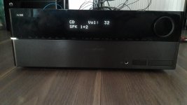
DS preamp in a HK3490
Hello,
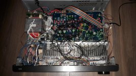
here is what I did with this gorgeous preamp. I consider this a functional prototype, so don't blame me for inappropriate wirings But I think, it is already a good example of what you can do with diy components. In this case, it greatly improved the original amp's performance.
What may be of special interest here is that I'm using serial potis to do all the tone controls with an Arduino. So far, I cannot hear any negative influences. But I must admit, that I don't have the equip to do accurate measurements.
Again a big thank you to Carl and the others who contributed to this preamp!
Cheers,
Frank
Hello,
here is what I did with this gorgeous preamp. I consider this a functional prototype, so don't blame me for inappropriate wirings
But I think, it is already a good example of what you can do with diy components. In this case, it greatly improved the original amp's performance. What may be of special interest here is that I'm using serial potis to do all the tone controls with an Arduino. So far, I cannot hear any negative influences. But I must admit, that I don't have the equip to do accurate measurements.
Again a big thank you to Carl and the others who contributed to this preamp!
Cheers,
Frank
Attachments
Last edited:
Nice job Frank!
Could you give us more detail on your circuit and Arduino implementation?
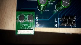
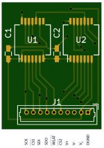
For the potis, I have used 2 MCP41HV51 devices per PCB to replace one of the original potis. These are high voltage SPI potis with separate analog and digital voltages.
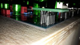
On the PCBs, there is only the 2 potis, 2 100nF caps and the connectors: on the bottom two pin headers to fit in the original poti holes (s. image in first post) and on the top side a Molex Picoblade for all the rest. The pinout is given in the attachments, the PCB layout as well.
The wiring is pretty much straightforward: The HK3490 offers a 5.6V supply and a +-15V supply. The 5V (via diode) I used for the Arduino and poti digital voltage, the +-15V for the preamp and the poti analog voltage.
Btw: I have soldered a relay on the mounting points for the direct tone switch. This can be powered by a 12V supply, which is also provided by the HK3490
Don't hestitate to ask further questions or give me hints how to improve this prototype
Frank
Attachments
For the potis, I have used 2 MCP41HV51 devices per PCB to replace one of the original potis. These are high voltage SPI potis with separate analog and digital voltages.
On the PCBs, there is only the 2 potis, 2 100nF caps and the connectors: on the bottom two pin headers to fit in the original poti holes (s. image in first post) and on the top side a Molex Picoblade for all the rest. The pinout is given in the attachments, the PCB layout as well.
The wiring is pretty much straightforward: The HK3490 offers a 5.6V supply and a +-15V supply. The 5V (via diode) I used for the Arduino and poti digital voltage, the +-15V for the preamp and the poti analog voltage.
Btw: I have soldered a relay on the mounting points for the direct tone switch. This can be powered by a 12V supply, which is also provided by the HK3490
Don't hestitate to ask further questions or give me hints how to improve this prototype
Frank
I'm afraid these electronic pots increase the distortion. Can you take measurements? Nevertheless, an interesting approach!
I'm sure they introduce some distortion. But in order to integrate the preamp with the rest of the amp, I needed to find a way to electronically control the tone controls. With this in mind, I think these potis are not so very bad - especially since they do not use AGND.I'm afraid these electronic pots increase the distortion. Can you take measurements? Nevertheless, an interesting approach!
I have no equip for measurements. But even in this prototype state, the amp even outperforms my Rotel. Good enough for me
Frank,
I find it hard to believe that swapping mechanical pots for digital pots adds noise and/or distortion. In my experience Microchip digital pots are a good choice for this project and your method to attach them to the project PCB is rather ingenious! I invite you to give us more details as to your build. For example do you have a schematic of your circuit? Which Arduino did you use? And are you willing to share the source to the controlling program? I am certain that most everyone here would be interested in anything that you might share.
I find it hard to believe that swapping mechanical pots for digital pots adds noise and/or distortion. In my experience Microchip digital pots are a good choice for this project and your method to attach them to the project PCB is rather ingenious! I invite you to give us more details as to your build. For example do you have a schematic of your circuit? Which Arduino did you use? And are you willing to share the source to the controlling program? I am certain that most everyone here would be interested in anything that you might share.
Last edited:
Thanks for the compliments!In my experience Microchip digital pots are a good choice for this project and your method to attach them to the project PCB is rather ingenious!
I don't know if in this case the added noise/distortion is measurable or even audible. Without measurements, I don't want to give rise to speculation. All I can tell is that I don't hear a difference to the mechanical solution.I find it hard to believe that swapping mechanical pots for digital pots adds noise and/or distortion
I use a Mega 2560 as I have many IO lines to connect to, e.g. the display and all the main amp controls. Additionally, there will be an Input PCB, probably with ~8 relays on it. These will need IOs, too. But if you only need to control the potis, even a Nano could do the job. All you need is the SPI interface and 6 CS lines. I added a quick drawing as attachment (please keep in mind that this is work in progress...).I invite you to give us more details as to your build. For example do you have a schematic of your circuit? Which Arduino did you use?
At the moment, I have the code in a VSTS git repo, and during the last two weeks, the change rate was very, very high. And even though it has ~1000 lines of code, now, there is still a lot of HMI functions missing (I have to reconstruct the whole amp controls, not only tone controls). Nevertheless, the potis are working, and everyone who is interested can send me a PM. Sharing the code is no problem for me, but at the moment, it would be a problem for those who try to use it - maybeAnd are you willing to share the source to the controlling program? I am certain that most everyone here would be interested in anything that you might share.
For those who want to build something on their own, I recommend the library here, which offers easy access to the potis.
P.S. The more precise the questions, the more precise the answers
Attachments
Microchip digital pot
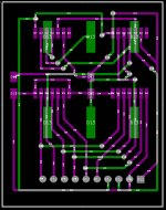
For those who are interested: Here is the Gerbers for the Poti PCBs.
Btw:
At the time when I designed the PCB, I had not yet completely read the datasheet. In the application notes they say, you should apply decoupling caps between the analog voltages and AGND. Without this in mind, I only applied one cap between logical supply voltage and logical ground. If anyone can tell what's the best way to apply caps here, please let me know.
Attachments
Last edited:
Just do it!I'd love to incorporate arduino control into my self preamp, it'd be awesome!
- Home
- Source & Line
- Analog Line Level
- Doug Self Preamp from Linear Audio #5