The BOM specifies this for the PCB side, AMP which is TE now.

The BOM doesn't say btw which one to use on the cable side.
A matching one for the cable would be Mouser p/n 571-2-215882-0.
The BOM doesn't say btw which one to use on the cable side.
A matching one for the cable would be Mouser p/n 571-2-215882-0.
Why?BUILDERS NOTE: * XLR Pin1 Grounding *
Note that the IO PCB that I delivered ties pin1 to the internal circuit ground. This is not an uncommon practice for consumer gear and works as expected 99% of the time. If your desire is to ground the XLR Pin1 to the chassis you must use a different XLR connector than the one specified in the BOM. Instead use an XLR whose pins extend straight out the back rather than down to the PCB. Doing this allows you to route pin 1 to the chassis using a short wire. You will also need to run short wires between pins 2 and 3 to the PCB.
There are Neutrik connectors where all 4 contacts are independently routed out, regardless if they are horizontally or vertically mounted, made especially for this purpose. Like the standard NC3FAV ties pin1 to chassis (pin4) but the NC3FAV2 has all 4 contacts routed out independently.
This is why Neutrik is simply preferable than Amphenol or any other brand for XLR connectors. Not to speak that the same Neutrik's are available as well with the whole ring made out of metal for making a 100% EMI shield around the connector itself (compare NC3FBH2 to NC3FAH2 for horizontal mount, denoted by "H" or NC3FBV2 to NC3FAV2 for vertical mount, denoted by the "V"). The "2" denotes that pin1 is independently routed out and not tied to pin1. Then, on the PCB do whatever you want, have a configurable jumper, etc.
The male MAV has always 4 separate pins on the back.
And same play here with MAV and MBV or MAH and MBH.
"M" stands for male, "F" stands for female, easy not.
Edit:
I noticed the Amphenol XLR connectors in the BOM - I would never use those, but NC3FAH2 and NC3MAH or the more expensive (pin compatible and) 100% EMI shielded NC3FBH2 and NC3MBH - they all are horizontally mounted and with separated pins for ground and chassis on the solder side. Maybe the IO PCB have to be remade.
Last edited:
Any recommendations for the power entry and power switch?
I was looking at Schaffner's FN9244-1-06 (1A version) for its filtering properties. https://www.mouser.ca/datasheet/2/355/FN9244-1036117.pdf
I was looking at Schaffner's FN9244-1-06 (1A version) for its filtering properties. https://www.mouser.ca/datasheet/2/355/FN9244-1036117.pdf
'YES!' Check your personal messages ...Are there any more PCB kits available for this project?
Just wondering if there is a current BOM for the power supply? This dropbox link is expired and I searched this thread and didn't see anything. I think I have most of the needed parts but would love to be able to double check before I get to this. Finally beginning the preamp build after putting off for over a year and waiting on parts availability.Revised Power Supply BOM
Hello all,
George Brooke being the diligent sole that he is has improved the Power Supply BOM, saving all of you from some of my bad habits. Thank you George!
The revised Power Supply BOM is here: https://dl.dropboxusercontent.com/u/33294265/DSELF_PWR_SUPPLY_BOM_01.xls
Just wondering if there is a current BOM for the power supply? This dropbox link is expired and I searched this thread and didn't see anything. I think I have most of the needed parts but would love to be able to double check before I get to this. Finally beginning the preamp build after putting off for over a year and waiting on parts availability.
We've shipped a couple of different power supply PCBs in the kit.
Which one do you have? There should be version numbers on the bottom
Can I replace NE5534AN with NE5534AP ?
SureCan I replace NE5534AN with NE5534AP ?

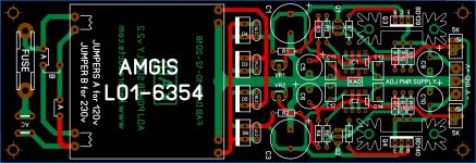
Yes it is that one. Thanks!Does the PCB look like this?? I'll will post details ...
I am trying to use the power supply schematic in post 2053 to come up with the BOM for the 2.2 power supply. I think I have most of it but the image you shared is blurry in spots so...
Can't quite tell what the values are for:
r5-r15
Also--while I am it...on the input board what goes in the spot circled in this image:

Can't quite tell what the values are for:
r5-r15
Also--while I am it...on the input board what goes in the spot circled in this image:
Never mind on the resistor values, I found the schematic as posted at 1893.
Assuming that the circled area on the image is for a small value capacitor but but what value?
Hopefully this is my last question but--on the power supply, the trimmer resistors--I'm assuming a basic Bournes 5k trimmer like this is ok: PV36W502C01B00
Thanks again.
Assuming that the circled area on the image is for a small value capacitor but but what value?
Hopefully this is my last question but--on the power supply, the trimmer resistors--I'm assuming a basic Bournes 5k trimmer like this is ok: PV36W502C01B00
Thanks again.
- Home
- Source & Line
- Analog Line Level
- Doug Self Preamp from Linear Audio #5