Thanks for clarifying.
I just realized that your schematic is from the simulation, so you can actually switch a relay") As for the shorted output. I reread the posts above. Now have another question, how do the transistors recover from the cutoff? Is there a chance to have a 'pop' from them once unmuted or it is a non issue here?
As for the shorted output. I reread the posts above. Now have another question, how do the transistors recover from the cutoff? Is there a chance to have a 'pop' from them once unmuted or it is a non issue here?
I am not so skilled in discrete electronics ... well most of electronics ... but anyway I am trying to understand and follow your project development with interest.
Oleg
I just realized that your schematic is from the simulation, so you can actually switch a relay
As for the shorted output. I reread the posts above. Now have another question, how do the transistors recover from the cutoff? Is there a chance to have a 'pop' from them once unmuted or it is a non issue here?I am not so skilled in discrete electronics ... well most of electronics
... but anyway I am trying to understand and follow your project development with interest. Oleg
Thanks for clarifying.
I just realized that your schematic is from the simulation, so you can actually switch a relay
I am not so skilled in discrete electronics ... well most of electronics
Oleg
You are in fact quite good in electronics from your comments, and I'm in the middle of learning it as doing it myself. Glad to have your attention on this little project.
I have the same question about the recovery too. If it pops we lose much of all the points of having a muting relay. I'll put it to the simulation and see what it would tell us.
Last edited:
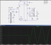
I simulated the behavior of the buffer recovering from cutoff at the moment the muting is released. I put in a pair of MOSFETs wired up as a solid state relay to mimic a relay contact. The signal level at input is 1Vrms.
First picture is for R10=150 ohm, no transistor cutoff,
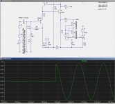
2nd picture has R10=47 ohm, transistors cutoff during part of negative cycle, but muting releases during positive cycle.
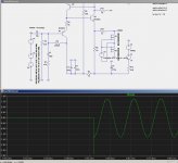
3rd picture also has R10=47 ohm, muting releases during negative cycle in the middle of transistor cutoff
The spike in picture 3 looks bad. It has 2uS at its base and the amplitude can quite possibly drive a power amp to clip if the LPF at the power amp input isn't aggressive enough.
So what are the options that we have for the muting?
1) increase R10 to 330 ohm and there will be no spikes up to 2.33 Vrms at the input. The buffer will then end up with an output impedance some would wish lower.
2) scrap the shorting to ground scheme and leave the relay contact in the audio path, as it is in the current layout
3) any other ideas?
First picture is for R10=150 ohm, no transistor cutoff,
2nd picture has R10=47 ohm, transistors cutoff during part of negative cycle, but muting releases during positive cycle.
3rd picture also has R10=47 ohm, muting releases during negative cycle in the middle of transistor cutoff
The spike in picture 3 looks bad. It has 2uS at its base and the amplitude can quite possibly drive a power amp to clip if the LPF at the power amp input isn't aggressive enough.
So what are the options that we have for the muting?
1) increase R10 to 330 ohm and there will be no spikes up to 2.33 Vrms at the input. The buffer will then end up with an output impedance some would wish lower.
2) scrap the shorting to ground scheme and leave the relay contact in the audio path, as it is in the current layout
3) any other ideas?
Attachments
Last edited:
The cap at the input is not for protection against incoming DC, but for preventing the pot from trimming the buffer offset, although it happens to perform the DC blocking duty. I'll see how stable the output offset goes then decide on an output cap at Rev.2 layout. It's supposed to be unnecessary by the excellent thermal cancelling design and the use of matched dual transistors.
I'd ask Keantoken. I think you've found a non-issue.
There's different regulators. JP likes a bunch of LDO's. Salas often ok's his designs, and others may. The TL431 as a regulator for capacitor multiplier worked well for me.
I'd ask Keantoken. I think you've found a non-issue.
There's different regulators. JP likes a bunch of LDO's. Salas often ok's his designs, and others may. The TL431 as a regulator for capacitor multiplier worked well for me.
Directly connecting a volume pot to the buffer makes it become part of the DC bias circuit, and the result has often been a widely known issue -- scratchy wiper noise, rather than a non-issue. Simulation shows a 20mV offset variation at the output of a Kuartlotron buffer when turning a 100K-ohm pot end to end with the wiper directly connected to the input as R8 in the original design. I have not built a Kuartlotron buffer so cannot comment. However the coupling cap in the layout can be easily jumpered out if not desired. In the layout design the caps sit over a bunch of SMD parts, so you don't even pay for the PCB area for them. It's very much a no brainer to me.
Did you check out the low noise LDO regulators in the first post schematic? How do you like them?
I simulated the behavior of the buffer recovering from cutoff at the moment the muting is released. I put in a pair of MOSFETs wired up as a solid state relay to mimic a relay contact. The signal level at input is 1Vrms.
First picture is for R10=150 ohm, no transistor cutoff,
2nd picture has R10=47 ohm, transistors cutoff during part of negative cycle, but muting releases during positive cycle.
3rd picture also has R10=47 ohm, muting releases during negative cycle in the middle of transistor cutoff
The spike in picture 3 looks bad. It has 2uS at its base and the amplitude can quite possibly drive a power amp to clip if the LPF at the power amp input isn't aggressive enough.
So what are the options that we have for the muting?
1) increase R10 to 330 ohm and there will be no spikes up to 2.33 Vrms at the input. The buffer will then end up with an output impedance some would wish lower.
2) scrap the shorting to ground scheme and leave the relay contact in the audio path, as it is in the current layout
3) any other ideas?
3) Use output caps, shorting to GND won't be a problem then. Text in BOM:"only install muting relay when output caps are used"....
Or leave it like it is now and use excellent relays
Last edited:
3) Use output caps, shorting to GND won't be a problem then. Text in BOM:"only install muting relay when output caps are used"....
Or leave it like it is now and use excellent relays
Thanks, Jean-Paul.
I've been working on a muting control that involves the input selection relays. Because the noise problem with muting to ground only happens at presence of input signal (exceeding certain level), it can be resolved by removing the input signal prior to shorting output to ground, and by keeping the input absent until after the output muting has been released.
I attached the schematic pdf with the new relay control that operates the muting relay and the input selection relay in tandem. The off-board relay control header also has the control signal, just in case one would like to use a separate input relay PCB.
Attachments
I was hoping to receive the Linear Tech low noise LDO regulator samples by Friday, and have been prepared to start assembling the preamp on the weekend. To my disappointment nothing was in the mail.
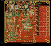
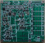
These regulators are the finest pin spacing (0.65mm) components in this design, I would definitely solder them first before anything else goes on the board. Can't do anything other than making a mock-up with all the through-hole parts to make sure things work together.
These regulators are the finest pin spacing (0.65mm) components in this design, I would definitely solder them first before anything else goes on the board. Can't do anything other than making a mock-up with all the through-hole parts to make sure things work together.
Attachments
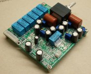
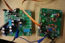
looking like a very promising board!Received the LTC LDO regulator samples and managed some soldering iron time. This is the look of the PCB with all SMDs soldered down, all done manually with a regular soldering station with temperature control.

Wow nattawa.
I need new eyes for this job
Merry Christmas
Merry Christmas to all!
Haha, you probably don't need even new glasses. It was not as hard as it appeared,
speaking from experience.The thing works, flawlessly.
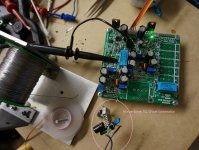
The buffer, the low noise power regulator system, and the muting control all work. There was an error in the negative LDO regulator connection in the schematic but was easily corrected by re-wiring a resistor on the PCB.
The buffer buffers a square wave test signal that has a transition time of about 10 nS beautifully.
Attachments
Sure I will. Beyond simply telling how I like the sound, I have two unity gain preamps in hand that I can compare the Kuartlotron against. One of them is McCormack TLC-1 that Stereophile highly recommends, the other is my other DIY-ed preamp that was based on member OPC's (Owen of Ottawa) "The Wire" headphone amp in SE-SE flavor. I'll need to make a 3-1 selection switch to allow switching in and out the preamps quickly and handily.
Kuartlotron Takes Bubba-Jag
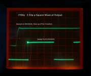
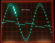
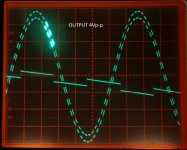
I posted a jagged sine wave test signal generator that I call "Bubba-Jag" on the solid state forum, and our Kuartlotron has become its first customer. The Bubba-Jag
The scope screen shots of the input and output wave form show Kuartlotron's excellent response to the fast transition edges throughout the sine wave cycle. The sine wave is about 1.7KHz in frequency, and the imposed square wave is 32x that at about 54KHz. The B-sweep (close-up of the highlighted part) is at 5uS/Grid.
Attachments
- Status
- This old topic is closed. If you want to reopen this topic, contact a moderator using the "Report Post" button.
- Home
- Source & Line
- Analog Line Level
- Kuartlotron Preamp Implementation, SMD Heavy.