My point is: Will the noise/distortion cancellation that is described in Bruno´s paper work on the way the MAX device produces harmonic distortion/noise?
Maybe Bruno can chime in on this?
The rise in distortion @low freq, that is seen in the paper, was related to the log. potmeter Bruno inadvertently used first and was eliminated with a linear potmeter, so the MAX device should be fine in this regard.
Maybe Bruno can chime in on this?
The rise in distortion @low freq, that is seen in the paper, was related to the log. potmeter Bruno inadvertently used first and was eliminated with a linear potmeter, so the MAX device should be fine in this regard.
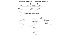
Now see what happens when adding a resistor R in one leg of the pot.
[Y*(A*I + B*I^2)] / [(100-Y)*(A*I + B*I^2)]+I*R =([Y] / [100-Y]) * (A*I + B*I^2) / ({A+R}*I +B*I^2)
Without going into further details, it is obvious that the elegant elimination of non-linearity is no longer available.
But, what you could do is to add a SECOND pot, exactly the same as the volume pot, thus having the same non linearity.
In that way, you can use the first pot for volume setting and the second pot as a variable resistor Z.
The algorithm would then become:
[Y*(A*I + B*I^2)] / [(100-Y)*(A*I + B*I^2)]+Z*(A*I + B*I^2) =([Y] / [100-Y+Z]) * (A*I + B*I^2) / (A *I +B*I^2) = [Y] / [100-Y+Z]
And again, the non-linearity has now been completely removed, and also [100-Y+Z] can never become zero, preventing a gain of infinity.
Hopes this explanation helps to get this problem out of the way forever.
Hans
Hi Hans,
If one choose to add 2nd pot as a variable resistor Z, how such a composite should be wired and whether both pots should be on the same axis in order to have the same rotational angle/value...like in sch below?
Attachments
Linearity of the pot in terms of the resistance ratio is in this topology a necessary condition for the elimination of distortion.My point is: Will the noise/distortion cancellation that is described in Bruno´s paper work on the way the MAX device produces harmonic distortion/noise?
Maybe Bruno can chime in on this?
The rise in distortion @low freq, that is seen in the paper, was related to the log. potmeter Bruno inadvertently used first and was eliminated with a linear potmeter, so the MAX device should be fine in this regard.
However, a sufficient condition is that the pot used does not have other sources of nonlinear distortion, which is not the case with the Maxim device.
Possibilities for using an electronic pot have been discussed earlier in the thread. Apparently, there is a Japanese pot that can be used in the feedback path, but I don't remember the model number any more.
Regards,
Braca
Linearity of the pot in terms of the resistance ratio is in this topology a necessary condition for the elimination of distortion.
However, a sufficient condition is that the pot used does not have other sources of nonlinear distortion, which is not the case with the Maxim device.
Possibilities for using an electronic pot have been discussed earlier in the thread. Apparently, there is a Japanese pot that can be used in the feedback path, but I don't remember the model number any more.
Regards,
Braca
Ok thanks.
I think I will drop the MAXIME idea after all.

I found the discussion mentioned above; I think it explains why this is not a viable idea:
http://www.diyaudio.com/forums/anal...p-balanced-volume-control-31.html#post4622524
Regards,
Braca
http://www.diyaudio.com/forums/anal...p-balanced-volume-control-31.html#post4622524
Regards,
Braca
I found the discussion mentioned above; I think it explains why this is not a viable idea:
http://www.diyaudio.com/forums/anal...p-balanced-volume-control-31.html#post4622524
Regards,
Braca
That discussion is pretty weird, as they conclude that it is very difficult to implement a digital vol.control in the same way as the analog potmeter, but this is exactly what a lot of these digital potmeters are designed to do.
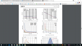
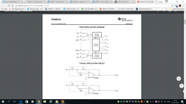
Look at the screenshot. This is a TI device, and they have no distortion measurements for that, but the topology is the same as the AD5116.
Typical application is precisely how it would be used in Brunos preamp-
Attachments
Well, I wasn't aware of the TI chip at the time.
While this device can be used in the feedback path, there are several points to observe before considering its use in this project.
Gain range: at least in my case, the -23.5 to +23.5dB range of the pot is not very useful because most signal sources with differential output have an output level of 4.2V. With the max. attenuation of the pot, the preamp would still send 280mV to the power amp, which amplified by 26dB (typical power amp gain) would put 5.6V at the speaker terminals. This is quite loud with most loudspeakers.
I've built two such preamps, one each with the mechanical pot and with the relay-switched attenuator, and both have a maximum gain of 6dB.
The other point wih the TPL8002-25 is that it is a low-voltage device. Should for whatever reason the voltage difference across the pot exceed the -4 to +4V limit, which is possible (e.g. 4.2V invertedby the output stage without gain ), the device may be destroyed.
Finally, the lack of the THD figures in the DS tells me that this pot is not meant to be used in a HiFi system.
Regards,
Braca
Well, I wasn't aware of the TI chip at the time.
While this device can be used in the feedback path, there are several points to observe before considering its use in this project.
Gain range: at least in my case, the -23.5 to +23.5dB range of the pot is not very useful because most signal sources with differential output have an output level of 4.2V. With the max. attenuation of the pot, the preamp would still send 280mV to the power amp, which amplified by 26dB (typical power amp gain) would put 5.6V at the speaker terminals. This is quite loud with most loudspeakers.
I've built two such preamps, one each with the mechanical pot and with the relay-switched attenuator, and both have a maximum gain of 6dB.
The other point wih the TPL8002-25 is that it is a low-voltage device. Should for whatever reason the voltage difference across the pot exceed the -4 to +4V limit, which is possible (e.g. 4.2V invertedby the output stage without gain ), the device may be destroyed.
Finally, the lack of the THD figures in the DS tells me that this pot is not meant to be used in a HiFi system.
Regards,
Braca
The TI device was just to illustrate, that ALL the digital potentiometers can be used this way.
The resistance change in the TI is not ideal. A device like the AD5111 would probably be better, but that has to be examined closer.
So many different threads I read about the BPBBP...
On another thread, there was a recent discussion about what exactly it is about the linear pot that is important.
It came down to charge density of the track on each side of the wiper, rather than resistance. I'm not so sure that applies to these devices.
On another thread, there was a recent discussion about what exactly it is about the linear pot that is important.
It came down to charge density of the track on each side of the wiper, rather than resistance. I'm not so sure that applies to these devices.
Well, whether all digital pots can be used within the feedback path may realy be of academic interest only.The TI device was just to illustrate, that ALL the digital potentiometers can be used this way.
The resistance change in the TI is not ideal. A device like the AD5111 would probably be better, but that has to be examined closer.
The important point in this application is whether a solution with a digital pot is able to deliver results comparable to a linear pot in the NFB path.
Even MUSES72320 is in the recommended application really only a standard pot feeding the signal to the noninverting input of the output stage, against which Bruno explicitly advised, and which can't be realised with the current PCB.
Re. the AD5111 chip, you might want to consider that it is also a low-voltage device, that the THD is -80dB, and that the DS recommends it for open-loop applications. There is also some digital feedthrough which gives me an uneasy feeling in this case.
I would genuinely like to see a digital pot applied in the NFB path, and especially the THD results of such an application.
Regards,
Braca
Well, whether all digital pots can be used within the feedback path may realy be of academic interest only.
The important point in this application is whether a solution with a digital pot is able to deliver results comparable to a linear pot in the NFB path.
Even MUSES72320 is in the recommended application really only a standard pot feeding the signal to the noninverting input of the output stage, against which Bruno explicitly advised, and which can't be realised with the current PCB.
Re. the AD5111 chip, you might want to consider that it is also a low-voltage device, that the THD is -80dB, and that the DS recommends it for open-loop applications. There is also some digital feedthrough which gives me an uneasy feeling in this case.
I would genuinely like to see a digital pot applied in the NFB path, and especially the THD results of such an application.
Regards,
Braca
You are right about the 5V max issue and that could be the reason for not trying these Digital pots. The -80 dB distortion is not so much a worry for me as Bruno states in his paper, that wiper contact in a normal potentiometer is a source of distortion, and that dosent show up in his measurements. Could be the distortions in the digital pot is attenuated to a much lower level?
Maybe one should look at a R2R DAC and use it as Hans circuit?
Many years ago I build a couple of very good sounding volume control using a parallel data fed logarithmic R2R DAC AD7112.
It can withstand +/-25V has max.-91dB distortion and is 7 bits long. To avoid very high gains, it could be restricted to a certain range of digital numbers ...???
This what Bruno says in his article. Not that it is in this circuit, but normally it is. And I would guess the same holds true for the digital switches in the digital potmeter and therefore maybe not an issue in this circuit..Is the wiper a source of distortion in this circuit? It's not carrying signal in any way so what kind of distortion are you thinking of?
The wiper is at some signal voltage.Is the wiper a source of distortion in this circuit? It's not carrying signal in any way so what kind of distortion are you thinking of?
+IN & -IN are at audio ground voltage.
There is a voltage across the -IN resistor.
The wiper passes current.
The wiper resistance is not the only source of distortion in potentiometers, passive or digital.
In the case of AD5111, the THD figure of -80dB refers to something that may be called "insertion THD"; as specified in the DS, it refers to the signal at the wiper in the pot centre position being distorted by so much with regard to the input signal.
A good mechanical pot is much better than that.
I may be overly cautious, but I still would not insert a device with a THD of -80dB into a circuit having a THD of -120dB with a passive pot.
Regards,
Braca
The wiper resistance is not the only source of distortion in potentiometers, passive or digital.
In the case of AD5111, the THD figure of -80dB refers to something that may be called "insertion THD"; as specified in the DS, it refers to the signal at the wiper in the pot centre position being distorted by so much with regard to the input signal.
A good mechanical pot is much better than that.
I may be overly cautious, but I still would not insert a device with a THD of -80dB into a circuit having a THD of -120dB with a passive pot.
Regards,
Braca
I know a good potentiometer is better than that, but a lousy one that Bruno used is maybe not better, that is my point. But it must be tested to see.
I put in a preamp before the pot in my system.
this knocks noise and distortion down 20db. wiper drives a tube tone stage
115db s/n at 1 watt output with .0003 distortion using opa2134. ( 2nd opa2134 in place of tube)
the only sacrifice is input headroom and that is still 20db
this knocks noise and distortion down 20db. wiper drives a tube tone stage
115db s/n at 1 watt output with .0003 distortion using opa2134. ( 2nd opa2134 in place of tube)
the only sacrifice is input headroom and that is still 20db
Last edited:
- Home
- Source & Line
- Analog Line Level
- BPPBP - Bruno Putzey's Purist Balanced Preamp (well a balanced volume control really)