Jens, read your site, very impressive. Now I understand as well why you want to go with normal opamps. The proposed super-active-x-over would become huge when using discrete opamps.
Nevertheless, the question is what is the target here. I would be interested in a model which has for 2 way one LP and one HP and that's it.
For three-way it would be 2 HP and 2 LP, so that the bass and the tweeter goes not through a bandpass.
I guess everybody needs regluators, inut and output-buffers.
It would be great to have on a separete board the option to EQ stuff like a super-treble-gain-stage.
I am with Promitheus: I want as well discrete opamps.
Best Regards
You guys go ahead, I'll make my own boards, I won't accept anything that isn't in the spirit of the original moamps design and the pass design, ie balanced operation, discrete ICs and all adjustable parameters.
Mostly, I have big problem with someone with a clear commercial intent taking the whole thing over and making it a profit endeavor. Although it doesn't break any law it breaks my balls since I didn't make any money with the AlephX board.
Mostly, I have big problem with someone with a clear commercial intent taking the whole thing over and making it a profit endeavor. Although it doesn't break any law it breaks my balls since I didn't make any money with the AlephX board.
their putting up resistance
"for instance with 8 resistor you can achieve 256 combinations. like I think Nelson Pass uses in his crossover."
No he doesn't......... read the manual.
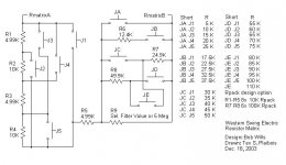
I looked a parallel resistor scheme. The problem it is not logical to program! There is a tremendous ease in use when you move a jump one to the right to increase frequency and one to the left to decease frequency.
However............ I did come up with a matrix that has more steps, less resistors, and a constant increment of 5K ohms per setting (jumper JB allows 2.5K increments that over lap a large part of the JA and JC range). For the 5K increments, only one jumper at a time is moved except when crossing the 25K/35K, 50K/55K, or 75K/80K step, which requires two jumpers to change. There is also no way to wire a short with the wrong jumper setting. There is only one jumper per 5 row section, R9 is to provide a DC path in case all JA to JE jumpers are pulled or to mount pot or audiophile resistor (if a final resistor value is chosen). The 5 row jumper sections also make it easy to see the position of the jumper. Having jumpered computer boards with 8 and more rows of jumpers I have bad memories of sticking the jumper on the wrong pin, after running out of fingers on my free hand to count with. Whatever jumper scheme you use lay all of them out with the same orientation and preferable left to right with increasing frequency increments! I have posted it before but here it is again:
"for instance with 8 resistor you can achieve 256 combinations. like I think Nelson Pass uses in his crossover."
No he doesn't......... read the manual.
I looked a parallel resistor scheme. The problem it is not logical to program! There is a tremendous ease in use when you move a jump one to the right to increase frequency and one to the left to decease frequency.
However............ I did come up with a matrix that has more steps, less resistors, and a constant increment of 5K ohms per setting (jumper JB allows 2.5K increments that over lap a large part of the JA and JC range). For the 5K increments, only one jumper at a time is moved except when crossing the 25K/35K, 50K/55K, or 75K/80K step, which requires two jumpers to change. There is also no way to wire a short with the wrong jumper setting. There is only one jumper per 5 row section, R9 is to provide a DC path in case all JA to JE jumpers are pulled or to mount pot or audiophile resistor (if a final resistor value is chosen). The 5 row jumper sections also make it easy to see the position of the jumper. Having jumpered computer boards with 8 and more rows of jumpers I have bad memories of sticking the jumper on the wrong pin, after running out of fingers on my free hand to count with. Whatever jumper scheme you use lay all of them out with the same orientation and preferable left to right with increasing frequency increments! I have posted it before but here it is again:
Attachments
Adjustment of freq
Hello,
With balanced operation, how do you get around the component variation. I mean it's fine to have balanced circuit, bu what if the two "halves" are not identical, how does this affect performance?
What kind of adjustment is the best, moamps resistor ladder or something else (multi turn pots or a multi position switch?)
\Jens
I guess I'll also build my own boards, because I'd like to have the origininal moamps design. Besides, is not so difficult to build oneself another module to equalize whatever woofer you may meet.
BTW, JensRasmussen, thanks for your interest, your ideas look very interesting.
BTW, JensRasmussen, thanks for your interest, your ideas look very interesting.
To grataku,
To grataku,
I tried to email you, but it was not possible. Let me clear a couple of things up.
I have worked on a similar project as the one posted I this thread for some time now. The work is done in my spare time, and is completely non profit. I love signal processing and saw this as a chance to help out, since more and more people are making active filters.
Many people find them a bit difficult, why I made the manual I referred to earlier in the thread. I hope it has cleared up some questions, and even better made people understand that filters not are all that difficult.
I did not take over moamps design, look at the schematics I posted, the circuit is changed/improved to get rid of the problem with gain in the pass band. Furthermore our website has been created to allow people to download documentation of our designs for their own education and to enable people to make similar project them selves.
Please read our about. Thank you
\Jens
I'm also desiring a simpler crossover than what Jens is proposing, and moamp's design fits my needs (and not only mine it seems...)
IMHO there should be a thread-splitting, since this one is named "MOX", and the discussion is getting too distant from the original topic.
Among all those who are interested in building moamps' design, is there anyone willing to organize a PCB run?
Cheers
Andrea
IMHO there should be a thread-splitting, since this one is named "MOX", and the discussion is getting too distant from the original topic.
Among all those who are interested in building moamps' design, is there anyone willing to organize a PCB run?
Cheers
Andrea
gratatu
I have been following this thread with great interest from the beginning.
Who on this thread are trying to make a profit ????????????
If you post accusations, then please also put the receivers name in it!
We are many on diyaudio, who offers our circuits, layouts and help for free, - just for the fun of making diy-audio........
I understand this as well as a non-profit-project and I have not seen any prices for pcbs yet which would indicate that anyone wants to make money out of it.
A commerical product which seems to fit quite the spec-pack is http://www.borbelyaudio.com/xover.pdf where you can get as well pcbs only: Discrete class a opamps, configurable between 6db-18db, input and outputbuffer and regulator (this one could be better) on board...more or less all we asked for and a nice outlook how the boards of the MOX could look like.
By the way: what do you guys think about that one ?
The usual CATastrophe
This is getting surreal, and as entertainment it's great. As for useful progress ............. well, it's sort of trying to herd cats.
All the information on filter Qs and equal value Sallen Key topology has been discussed in a few threads on the forum. When every one gets done running in circles I would suggest someone design a modular system built around a second order HP and LP filter section with a follower input to isolate the filter response from a level control. Design it for an 8 pin dip and make a discrete op amp module with an 8 pin DIP mounting legs (and a ground terminal to carry ground to the discrete op amp board). I would do SMT op amps with a DIP adapter and I seem to remember some that were quite reasonable in price (Brown Dog?). A buffered op amp could be built on a similar modular PCB. Leave about 4 square inches around the DIP connector on the main board for clearance.
SOMEONE GET FLUFFY BEFORE THE ARM FALLS OFF THAT COUCH !!!
Attachments


There's one in every crowd
You can always solder the machine pins from the adaptor to the board
Gold pin headers and machine sockets sound pretty decent ........ be sides how am I going to sell everyone a new amp module every 6 months. I think some of front ends of Mr. Pass X amps are modular.
JOE DIRT® said:LMAO Fred....you really get anal when you want to.....I keep it suddle
a modular approach is good for a new design but for the final approach a one board solution is the way to go in respect to sound quality
DIRT®
You can always solder the machine pins from the adaptor to the board
Gold pin headers and machine sockets sound pretty decent ........ be sides how am I going to sell everyone a new amp module every 6 months. I think some of front ends of Mr. Pass X amps are modular.
Attachments
Guess I will second the opinion that I'd prefer to stay pretty much with Moes design principles in this project...
I would agree, stay with the MOX design. I'm planning on using a different buffer input and probably Borbleys balanced line output to each section. If my speaker project will permit I would prefer to only use 6 dB filter slopes and not use a MOX active filter, but in case I can't then I would use one of the MOX filters for 12 dB.
The modular approach MOAMPS has designed fits my needs best.
BDP
- Status
- This old topic is closed. If you want to reopen this topic, contact a moderator using the "Report Post" button.
- Home
- Source & Line
- Analog Line Level
- MOX - active crossover