So in my case that would be a 1Khz signal at 2.5v (max input of preamp)
If "2.5V" is written in the user manuel, right.
Wow, i have had the same problem over the weekend but decided to use transfo instead to lower the voltage and balance the signal. I'm not sure it's ideal.
I used a pair of Hammond 804.
Envoyé de mon iPad en utilisant Tapatalk
I used a pair of Hammond 804.
Envoyé de mon iPad en utilisant Tapatalk
Look for something that employs some standard audio opamps, like this one. There may still be some construction goofs lurking inside (you never know with these Chinese kits), but at least parts quality looks quite good. (I saw another using the finest bottom-tier quality 100k pots and - presumably - original fake Signetics NE5532s.) This one only needs a mains transformer, I would guess with about a 15-0-15 V center-tapped secondary (or 2x 15 V).sgrossklass could you suggest a suitable preamp kit which would be less noisy, or at least the model of IC I should be looking for in a decent preamp?
Nothing fundamentally wrong there, even if maximum attenuation provided would be about 6 dB only. At least it gets you some CMRR.Wow, i have had the same problem over the weekend but decided to use transfo instead to lower the voltage and balance the signal. I'm not sure it's ideal.
I used a pair of Hammond 804.
Last edited:
Thanks for the link sgrossklass
Unfortunately i am running on batteries so i will have a hunt around for a NE5532 based preamp that runs on DC.
Unfortunately i am running on batteries so i will have a hunt around for a NE5532 based preamp that runs on DC.
Last edited:
If i wanted to use a Zener diode to limit the voltage would i need to apply it in the configuration shown on the picture below?
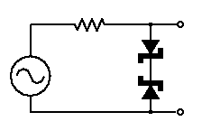
If so, what sort of value would i need the resistor to be?
Also as 0.5v zeners don't exist, is there a smart way of arraying a few bigger ones to reduce the max permissible voltage to 0.5v (the same way you can reduce resistor values by using them in parallel)
If so, what sort of value would i need the resistor to be?
Also as 0.5v zeners don't exist, is there a smart way of arraying a few bigger ones to reduce the max permissible voltage to 0.5v (the same way you can reduce resistor values by using them in parallel)
Last edited:
I don't know whether or not this has been written, but the input sensitivity of a power amplifier and voltage required to cause damage to said power amplifier are two completely different things.
Usually all that happens if you over drive the amplifier is that the output clips and it sounds terrible. If you keep increasing the voltage you will of course damage the amplifier, but most amps are designed with input stages that can accept a decent amount of voltage without breaking.
Then there is always the time when you want to listen to something that is extremely quiet and you actually need some additional oomph to make it audible.
Note also that the 520mV, as stated in the datasheet, is what's necessary for the power amp to output 100 watts into what is presumed to be a 4 ohm load. Then further down the page it says the 10% THD mark for the power amplifier is 107watts into the 4 ohm load. The 520mV specification is not an 'absolute maximum' it's just a figure. Most power amplifiers have input sensitivities between 500mV and 1V.
For this Musical Fidelity Power amplifier here.
Musical Fidelity AMS100 power amplifier Specifications | Stereophile.com
You can see that it's input sensitivity is 650mV for 100 watts into 8 ohms. Most digital sources output 2VRMS and most preamps used will add gain to that. You will not damage the power amplifier however by driving its input with more than 650mV.
Thanks for the info 5th Element,
The issue i have is that my preamp is outputting at 3.5v which is 6 times more than the input sensitivity.
If it were outputting at twice the input sensitivity i wouldn't be concerned, it is that big number that is making we worry for the amp if i do something stupid with the volume control which i inevitably will at some point 🙁
If so, what sort of value would i need the resistor to be?
Also as 0.5v zeners don't exist
Use 1k and a pair of ordinary diodes (1N4148) in parallel to clip at about 0.6V.
2 diodes in series each would be more appropriate here, otherwise he won't even make it to 0.5 Vrms. Besides, this sort of setup is appreciably nonlinear well below the limit; no wonder it's used as a soft-limiter.
Just use a resistive voltage divider at the output (as previously suggested) and be done with it. It works, gets the level down as needed, and reduces noise by the same degree to boot.
Just use a resistive voltage divider at the output (as previously suggested) and be done with it. It works, gets the level down as needed, and reduces noise by the same degree to boot.
.
This whole thing is getting so involved that I wanted to remind you of your own post #10.
You also illustrated the same concept in your own post #2.
Before you start rewiring your preamp, or buying a preamp for your preamp, I think you should give some more thought to your own idea, which in my opinion is the best thought so far.
In case you have the concept but you're shaky on the details, I'm posting the below illustrations. The first is the general principle, the second is a patch (connecting) cable that could be made up. Or might be made as a box, more likely. In any case you wouldn't have to open your preamp's case.
The shown resistance values are arbitrary, but could be as good a starting point as any.
Just thought I'd toss in 2 cents.
PS if you decide to do something like this don't mess with trying to solder 1/8" (3.5mm) stereo jacks. Buy a premade patch cable (with woven copper shield) and cut it to length. A "patch cable" by definition has a male connector on each end. Also called a "patch cord," also sold as electric guitar cables.
.
This whole thing is getting so involved that I wanted to remind you of your own post #10.
That's a great point AndrewT, i can put an extra resistor in series with the volume pot to force the maximum possible voltage to be lower.
You also illustrated the same concept in your own post #2.
Before you start rewiring your preamp, or buying a preamp for your preamp, I think you should give some more thought to your own idea, which in my opinion is the best thought so far.
In case you have the concept but you're shaky on the details, I'm posting the below illustrations. The first is the general principle, the second is a patch (connecting) cable that could be made up. Or might be made as a box, more likely. In any case you wouldn't have to open your preamp's case.
The shown resistance values are arbitrary, but could be as good a starting point as any.
Just thought I'd toss in 2 cents.
PS if you decide to do something like this don't mess with trying to solder 1/8" (3.5mm) stereo jacks. Buy a premade patch cable (with woven copper shield) and cut it to length. A "patch cable" by definition has a male connector on each end. Also called a "patch cord," also sold as electric guitar cables.
.
Attachments


Last edited:
- Status
- Not open for further replies.
- Home
- Source & Line
- Analog Line Level
- How to reduce a preamp output voltage?