Hi everybody,
I've been looking for simple schematics for a phono pre for a friend's setup and this one is about the least busy one I've found in the datasheet for the LM4562 opamp. I just don't understand the values that are circled in red. Are the resistors values supposed to be put in series with one another and that's why they have "+" signs? Are the cap values supposed to be put in parallel with one another and that's why they have "/" separating them? I've never seen this in a schematic yet.
It says that this is a passive design and seems fairly simple. Has anyone out there put this together and had success with it's curve being close to the RIAA standard?
Attachments
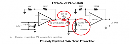
Not quite true. 5% tolerance on components may mean 10% tolerance on time constants. As high tolerance resistors are generally more easily available and cheaper than high tolerance capacitors there is a valid case for using, say, 1% resistors with 5% capacitors to get 6% accuracy. In addition, an RIAA network may use resistors to set the balance between LF and HF levels, while some capacitors may just set the transition frequency between these. Hence a cap value error may cause less change in response than a resistor error.
But what is the interferences from poles and zeros on the transfer function if values are affected by a large tolerance on resistors and caps ?
I think is possible to have a increase the precision of response dividing the poles one by one on its opamp . Is not best solution but is possible to use 5% tolerance components
I think is possible to have a increase the precision of response dividing the poles one by one on its opamp . Is not best solution but is possible to use 5% tolerance components
That's good news Reuben. I will probably order the parts I need for this project this weekend. I always use 1% R's and I'll go with 5% caps. I probably have enough film caps laying around to hit closer to the mark if it ends up being too far from what value it should be.
Thanks SY for that kabusa site reference to double check the values. I'll post up a frequency response for this circuit when it is finished.
Thanks SY for that kabusa site reference to double check the values. I'll post up a frequency response for this circuit when it is finished.
Last edited:
in addition to getting the absolute values right to match up to the time constants for equalization, it is also important to match values between the left/right channels to maintain balance across the frequency range.
measure your resistors and beg, borrow or steal a good cap meter; it will be worth it.
mlloyd1
measure your resistors and beg, borrow or steal a good cap meter; it will be worth it.
mlloyd1
WTF is with all this gain?!
Sup y'all. I mocked this circuit up on a breadboard real quick and I am blown away at how much gain this circuit is putting on the input signal!
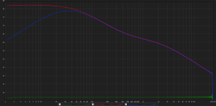
I thought that it was supposed to attenuate the highs and then boost the lower half like this:

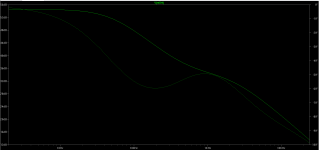
Instead, this circuit is boosting 20khz 15dB before even applying the boosted curve for a total max boost at 20Hz of 55dB!? I plan on using a volume control on it's output but still, this thing's noise floor is absolutely disgusting! It's like 57dB unweighted. Are record player's outputs really that weak that they need that much of a gain boost on the whole bandwidth?
See below for anyone not up to speed on the schematic that I'm talking about. The green trace graph is from LTSpice on it's predictions (thanks to Mooly for his tutorial in his signature), and the dark graph is the actual breadboard mockup results. The green trace is the soundcard's looped signal that feeds the input of this circuit. The blue trace is the circuit with a 1.5uF DC blocking cap on the output which is all I plan on doing for it's rumble filter.
Sup y'all. I mocked this circuit up on a breadboard real quick and I am blown away at how much gain this circuit is putting on the input signal!
I thought that it was supposed to attenuate the highs and then boost the lower half like this:

Instead, this circuit is boosting 20khz 15dB before even applying the boosted curve for a total max boost at 20Hz of 55dB!? I plan on using a volume control on it's output but still, this thing's noise floor is absolutely disgusting! It's like 57dB unweighted. Are record player's outputs really that weak that they need that much of a gain boost on the whole bandwidth?
See below for anyone not up to speed on the schematic that I'm talking about. The green trace graph is from LTSpice on it's predictions (thanks to Mooly for his tutorial in his signature), and the dark graph is the actual breadboard mockup results. The green trace is the soundcard's looped signal that feeds the input of this circuit. The blue trace is the circuit with a 1.5uF DC blocking cap on the output which is all I plan on doing for it's rumble filter.
Attachments
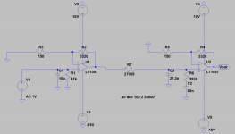
That circuit has two amplifying stages, each with a voltage gain around 23x, with a passive network between them. This suggests a mid-band gain around 50x, or 34dB - and LF gain around 54dB. A 'record player' output may be 5mV or thereabouts in the mid-frequency region so it needs some gain to bring it up to line levels. Unless you have a high output cartridge you may need more gain - it depends on what you are feeding.
Is your noise figure of 57dB measured or simulated?
Is your noise figure of 57dB measured or simulated?
It's measured, keep in mind it was all layed out on a breadboard so it will hopefully get a bit better once the project is completed in a box but it is still pretty bad. Usually my breadboard projects are around 90dB unweighted even with 10dB or so of gain in the lower frequencies.
Man, I sure hope I don't need anymore gain than that. The turntable is a Sony PS-LX250H. It has a built in RIAA EQ but I've read that it isn't very accurate with poor dynamics so I plan on A/B'ing the built in with this circuit at the end of the week.
Man, I sure hope I don't need anymore gain than that. The turntable is a Sony PS-LX250H. It has a built in RIAA EQ but I've read that it isn't very accurate with poor dynamics so I plan on A/B'ing the built in with this circuit at the end of the week.
Attachments
Yes, there will be a lot of gain.
The 20kHz gain is +15dB, after the massive amount of filtering, applied after the first stage of the amp.
The 20Hz gain is +54dB, but there is virtually no filtering of noise at that end.
If you assumed there was a maximum signal to noise ratio of 130dB, you could estimate the noise, but there is a bit of software that does all the calculation for you.
I bumped into it last week, can't remember the Thread that linked it.
Last edited:
Hi,
attached You find two basic parameter sets for simulating Phono Riaa circuits.
One for SE and the other for balanced Inputs.
They generate a preequalized low voltage (blue Recording curve), like a pickup does.
A circuit with perfect RIAA correction will yield a linear output which makes evaluation of the frequency-decicive parts easier.
jauu
Calvin
Attachments
clicking on the .asc version of the saved file gives this:
"There was a problem sending the command to the program"
What does that warning mean?
Do I have to do something?
As LTspice loads I always get a request from User Account Control
scad3.exe Yes or No?
Is that normal?
"There was a problem sending the command to the program"
What does that warning mean?
Do I have to do something?
As LTspice loads I always get a request from User Account Control
scad3.exe Yes or No?
Is that normal?
- Status
- This old topic is closed. If you want to reopen this topic, contact a moderator using the "Report Post" button.
- Home
- Source & Line
- Analog Line Level
- Phono Preamp Question...