I'm guessing it has something to do with the 55dB of gain because when I looked at the spectrogram of the noise floor in the audio band it had the same shape exactly as the EQ that it applies to the signal. I don't have an O-scope so I can't see if it was oscillating but I don't see why it would have been. I tried both the OPA2134 and NE5532 chips and the noise floor was identical.
@ Calvin -I'm sorry but I don't know how to load a .txt file into spice. I'm assuming that what the files are for?
@ AndrewT -About the user account control thing... Did you change the permissions of the program to administrator? If not, the description is in the link in Mooly's signature.
@ Calvin -I'm sorry but I don't know how to load a .txt file into spice. I'm assuming that what the files are for?
@ AndrewT -About the user account control thing... Did you change the permissions of the program to administrator? If not, the description is in the link in Mooly's signature.
Hi,
could it be You measured the stage with open inputs?
Then the 47k input resistor would generate such amounts of noise that 58dB noise measrement (by the way, referenced to what? dBV, dBu? or?) could be reasonable.
There are two measurements used.
1st with shorted input and 2nd with a connected pickup or pickup-dummy.
My noise simulations of the stage with LM4562 models and a AT-95E (410R, 400mH) resulted in ~25µVrms (-92dBV) for a shorted input and ~68µVrms (-83.3dBV) for the dummy pickup. With open inpout the noise voltage shot through the roof at ~470µVrms (-66.5dBV).
LTSpice sims the noise referenced to 1Vrms (hence dBV).
Simmed over the audio bandwidth 20Hz-20kHz.
The measurement with shorted input takes the 47k resistor out of the calculation and gives the lowest noise figures.
More practical is the use of a pickup or pickup-dummy as it´ll give more real
figures.
Of course it results in less impressive noise figures, is dependent on the pickup´s parameters and not standardized.
As such it´s seldomly used in marketing and for prospect figures.
jauu
Calvin
ps: attached is the simu-File of the MM-Stage of #1 with a couple of different OPAmp models
Attachments
Last edited:
I put the phono pre in the loop with my soundcard's input and output. The soundcard's noise floor is around -108dB and when I put in the phono pre it went up to the -57dB. I've never thought of shorting the inputs when I look at noise, I will try that in the future so I have another reference to compare with.
I guess that dB relates to voltage then but the max voltage out of this soundcard is 2Vrms so does that make it different from the 1Vrms you used for the LTSpice sims? I'm not totally sure what you are doing in the spice file here. Are you using the cartridges that you listed in this LTSpice file for the "pickup-dummy" then?
I guess that dB relates to voltage then but the max voltage out of this soundcard is 2Vrms so does that make it different from the 1Vrms you used for the LTSpice sims? I'm not totally sure what you are doing in the spice file here. Are you using the cartridges that you listed in this LTSpice file for the "pickup-dummy" then?
I put the phono pre in the loop with my soundcard's input and output.
You're looking at the soundcard's noise, amplified by 55dB. Use an attenuator between the soundcard output and the phono stage input, 50 dB or so.
Trouble!
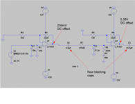
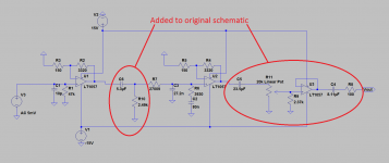
This circuit has me stumped. It worked fine as far as the frequency response but on the output before the DC blocking cap I was getting up to 6 volts of DC offset! I'm using NE5532's and I know they aren't the greatest chip for offset voltages and I know this circuit uses a lot of gain.
So to lower the offset at the output, (in this diagram) I used the 5.3uF cap after the first gain stage to stop the 234mV from being further amplified by the 2nd gain stage and it actually makes things worse! Now the circuit is not working correctly, and on the output before the final blocking cap I'm getting over 10V of DC!! LTSpice showed the circuit working with just slightly more rolloff on the low end from the added blocking cap after the first stage.
Do I need a resistor somewhere from the + pin on the op amp to ground or something like that? The obvious answer is to but a buffer in between the 2 stages and isolate the blocking cap from the input of the 2nd stage but I am out of PCB space and don't want to add stuff. Aaagghhh, I hate when things don't work!
This circuit has me stumped. It worked fine as far as the frequency response but on the output before the DC blocking cap I was getting up to 6 volts of DC offset! I'm using NE5532's and I know they aren't the greatest chip for offset voltages and I know this circuit uses a lot of gain.
So to lower the offset at the output, (in this diagram) I used the 5.3uF cap after the first gain stage to stop the 234mV from being further amplified by the 2nd gain stage and it actually makes things worse! Now the circuit is not working correctly, and on the output before the final blocking cap I'm getting over 10V of DC!!
LTSpice showed the circuit working with just slightly more rolloff on the low end from the added blocking cap after the first stage. Do I need a resistor somewhere from the + pin on the op amp to ground or something like that? The obvious answer is to but a buffer in between the 2 stages and isolate the blocking cap from the input of the 2nd stage but I am out of PCB space and don't want to add stuff. Aaagghhh, I hate when things don't work!
Attachments
That supply problem was with a makeshift split supply. I hooked a proper regulated split supply up and the rails stay +/-15V. The offset voltage on the 2nd stage output then goes to -13.53 with the DC blocking cap on the 1st stage's output!
When the DC blocking cap after the 1st stage is taken out, the circuit works as it should (see pic of freq res). The only thing I don't like is the 6V of offset on the 2nd stage output. When I put the blocking cap on the 1st stage output to try to help this problem, that's when things go nuts and the circuit stops working properly. I have continuity checked my a$$ off.
When the DC blocking cap after the 1st stage is taken out, the circuit works as it should (see pic of freq res). The only thing I don't like is the 6V of offset on the 2nd stage output. When I put the blocking cap on the 1st stage output to try to help this problem, that's when things go nuts and the circuit stops working properly. I have continuity checked my a$$ off.
Attachments
At what spot should I attach a resistor to ground and what value so that it will not affect the frequency response?
Right after C6. This will cause a LF rolloff, with f = 1 / ( 2 x 3.14 x R x C )
These offsets are due to the high Vos spec of the op amps. If the R is too large, the Ios will also cause additional offset voltage.
Last edited:
If the R is too large, the Ios will also cause additional offset voltage.
Thanks for the heads up rayma. I ended up increasing the value of the cap so I could lower the value of the resistor and got the offset down to 149mV on the 2nd stage output (before it's blocking cap). I feel much better about this circuit now. Looking back, I know I should have used something like the OPA2134 but whatever, there's always next time.
for minimum offset the Amplifier needs to see the SAME DC resistance at BOTH the -IN and +IN inputs.This circuit has me stumped. It worked fine as far as the frequency response but on the output before the DC blocking cap I was getting up to 6 volts of DC offset! I'm using NE5532's and I know they aren't the greatest chip for offset voltages and I know this circuit uses a lot of gain.
So to lower the offset at the output, (in this diagram) I used the 5.3uF cap after the first gain stage to stop the 234mV from being further amplified by the 2nd gain stage and it actually makes things worse! Now the circuit is not working correctly, and on the output before the final blocking cap I'm getting over 10V of DC!!
Do I need a resistor somewhere from the + pin on the op amp to ground or something like that? The obvious answer is to but a buffer in between the 2 stages and isolate the blocking cap from the input of the 2nd stage but I am out of PCB space and don't want to add stuff. Aaagghhh, I hate when things don't work!
This assumes that the input pair are perfectly matched and are at the same voltages internally and at the same temperatures. Inside an opamp, these assumptions are quite close to accurate. set the input DC resistances to the same values and sure enough the output offsets are usualy very low.
Now Look at your first opamp.
The -IN sees 150r//3k32
the =In see zero ohms through the driving voltage.
Equals small output offset due to the 150r DIFFERENCE in DC resistance.
Look at the second opamp.
The -IN sees 150r||3k32
the +IN sees infinite DC resistance.
Equals enormous output offset due to the enormous DIFFERENCE in DC resistance.
Change the lead on the first +IN for a copper trace to 140r
Adjust until the output offset is zero. How close will that adjusted value be to 150r||3k32?
repeat for the second opamp.
Last edited:
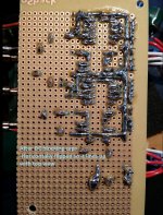
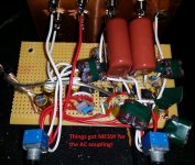
Finally got this project out of the way. For anyone searching this online it is the passively equalized RIAA phono preamplifier from Texas Instrument's LM4562 datasheet. I didn't use that chip, although I probably would've been better off if I had used something like the OPA2134. Instead I chose the good ol' NE5532.
Originally I followed the schematic to the letter only adding a cap per channel on the output to block any DC present. When I measured for DC on the output before that cap, it measured close to 6 Volts! At that point I realized that I picked the wrong chip for the job. Seeing as this is for a cheapo vinyl player (Sony PS-LX250H) I decided to keep the chips and add some DC blockers after stage 1 and stage 2. I then had the weird problem where the circuit would stop working once the caps after stage 1 would charge up so thanks to the helpful community here I realized that it needed a resistor after those caps for a path to ground.
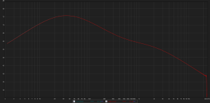
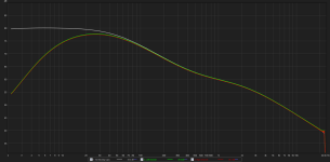
The circuit works as advertised and maxes out at around 57dB of gain at 30Hz. The frequency response graph is based on my soundcard which has an input impedance of around 4400k. Left and right channels end up very close to one another in output and EQ response. The actual application was for a friend's setup which has an input impedance of a bit less than 10k so the rolloff starts lower. After hearing it, I don't see the need for an added rumble filter.
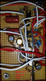
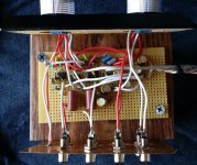
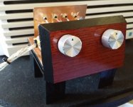
I also needed to add a volume control on the phono pre's output so I decided to use a dual linear 20k pot with a parallel resistor instead of a log pot. Thanks to all who have posted recently about this because it tracks like a dream! With a 10% dual pot, the L and R channels never differ more than .5dB and most of the time they are right on or very close to it. The other volume control you see is just for another input for my friend's system. It isn't in the pictures but I wrapped the top (bottom too) with 7 layers of thick aluminum foil and it makes contact with the copper piece that the RCA's mount to. The power rails/ground to the bypass electro caps is a twisted triplet with a close coupled signal ground that make contact with each other close to the PSU which I tapped from the subwoofer's DIY EQ circuit.
After putting the preamp inline with my soundcard's in/outs and attenuating my SC's output 58dB this circuit's noisefloor was around -78dB and -88dB with shorted inputs which isn't going to win any awards but it's probably due to how sloppy the whole thing ended up in it's wiring. Lots of afterthoughts and running out of room. With the volume control all the way up and no music playing, there is noticeable but tolerable 60Hz hum.
The Sony PS-LX250H player has a built in phono pre circuit. Sony PS-LX250H vs. DIY RIAA phono pre? We A/B'd them both with some Police and Phil Collins and the phono pre build immediately stood out with a more dynamic sounding low end (the kick drum jumped out of the mix) and a wider sounding soundstage. It was played on a 2.1 system. 2- DIY 3 ways with 12's, 250W a channel and a parametric EQ'd 12" sealed DIY subwoofer, 500W with around 20mm Xmax. A highlight of the night for me was YES' 90215 album. Definitely a good recording for the time.
Any and all criticism/advice is welcome, I won't get all "bentsnake" about it.
Originally I followed the schematic to the letter only adding a cap per channel on the output to block any DC present. When I measured for DC on the output before that cap, it measured close to 6 Volts! At that point I realized that I picked the wrong chip for the job. Seeing as this is for a cheapo vinyl player (Sony PS-LX250H) I decided to keep the chips and add some DC blockers after stage 1 and stage 2. I then had the weird problem where the circuit would stop working once the caps after stage 1 would charge up so thanks to the helpful community here I realized that it needed a resistor after those caps for a path to ground.
The circuit works as advertised and maxes out at around 57dB of gain at 30Hz. The frequency response graph is based on my soundcard which has an input impedance of around 4400k. Left and right channels end up very close to one another in output and EQ response. The actual application was for a friend's setup which has an input impedance of a bit less than 10k so the rolloff starts lower. After hearing it, I don't see the need for an added rumble filter.
I also needed to add a volume control on the phono pre's output so I decided to use a dual linear 20k pot with a parallel resistor instead of a log pot. Thanks to all who have posted recently about this because it tracks like a dream! With a 10% dual pot, the L and R channels never differ more than .5dB and most of the time they are right on or very close to it. The other volume control you see is just for another input for my friend's system. It isn't in the pictures but I wrapped the top (bottom too) with 7 layers of thick aluminum foil and it makes contact with the copper piece that the RCA's mount to. The power rails/ground to the bypass electro caps is a twisted triplet with a close coupled signal ground that make contact with each other close to the PSU which I tapped from the subwoofer's DIY EQ circuit.
After putting the preamp inline with my soundcard's in/outs and attenuating my SC's output 58dB this circuit's noisefloor was around -78dB and -88dB with shorted inputs which isn't going to win any awards but it's probably due to how sloppy the whole thing ended up in it's wiring. Lots of afterthoughts and running out of room. With the volume control all the way up and no music playing, there is noticeable but tolerable 60Hz hum.
The Sony PS-LX250H player has a built in phono pre circuit. Sony PS-LX250H vs. DIY RIAA phono pre? We A/B'd them both with some Police and Phil Collins and the phono pre build immediately stood out with a more dynamic sounding low end (the kick drum jumped out of the mix) and a wider sounding soundstage. It was played on a 2.1 system. 2- DIY 3 ways with 12's, 250W a channel and a parametric EQ'd 12" sealed DIY subwoofer, 500W with around 20mm Xmax. A highlight of the night for me was YES' 90215 album. Definitely a good recording for the time.
Any and all criticism/advice is welcome, I won't get all "bentsnake" about it.
Attachments
Last edited:
- Status
- This old topic is closed. If you want to reopen this topic, contact a moderator using the "Report Post" button.
- Home
- Source & Line
- Analog Line Level
- Phono Preamp Question...