Hi, sorry this is probably going to be some real newb questions, but here goes!..
I want to power a small signal circuit ( mixer ) of up about 50 dual op amps, which will be a mix of tl072's and ne5532's.
Would a well heat-sinked LM317 / 337 +-15 psu be sufficient to power this?
If so how do I work out the transformer it will need?
How do you test the current being draw through a split psu? Do you just break into the positive track and check the current there?
I have a dual 15v 50va toroidal transformer that I hope will be large enough for my project....
If one dual supply is not enough can I power two lots of rectifiers, caps, regs etc from the one tranny? Then I could power half the project from one lot of regulators etc...
Sorry if these are very basic questions, I have built many split power supplies and have successfully powered many op amp projects but this one is much bigger than anything I have done before and I don't want to melt anything!
Thanks
I want to power a small signal circuit ( mixer ) of up about 50 dual op amps, which will be a mix of tl072's and ne5532's.
Would a well heat-sinked LM317 / 337 +-15 psu be sufficient to power this?
I have a dual 15v 50va toroidal transformer
Your transformer is plenty, just use enough capacitance after the rectifiers, at least 1000uF. Also use enough heat sink on the regulators, for about 3W.
Of course, use all the usual decoupling caps at each op amp.
Last edited:
Rather than spoon feeding you.
Have a look at the data sheets for the TL072 and NE5532. Each should show you the maximum quiescent current for that op-amp.
Then have a look at the datasheet for the LM317 and LM337.
If each op-amp requires 50mA, the total supply requirement will be 50 x 50mA = 2.5A.
You don't want to be running the LM3xx close to its maximum current for too long for reliability stakes so you can either use more than one or use a bypass transistor to up the current.
In reality the current for each op-amp will probably be in the order of a few mA only so with adequate heatsinking the LM3xxT's will be OK.
Last edited:
The biggest problem is that many cannot read a datasheet.
K&D has given you the clue.
You MUST look at quiescent current AND at LOAD current.
The rail current into an opamp is roughly {quiescent current PLUS load current}.
If you have a maximum output voltage at the opamp of around 2Vac and a load of 2k then the load current is 2*sqrt(2)/2000 = 0.0014Apk (1.4mApk)
Now you need to estimate the capacitive load on the output. HF signals into parasitic and intended capacitive load can demand quite high load current. I'd just assume an average value of 1mApk for every opamp unless there is evidence that it is higher.
Our (example) totals are 5.5mA quiescent, 1.4mApk load, 1mA capacitive = ~ 7.9mApk
Multiplying by the number of opamp channels gives ~395mA
But only 50*5.5 = 275mA is continuous current draw.
The transformer MUST be able to supply that continuous DC current draw.
The absolute minimum AC rating of the transformer MUST be double the DC continuous current draw, i.e. >=550mAac.
I always recommend that the transformer be rated to operate @ ~50% of it's maximum rated continuous current draw. i.e. use a ~1.1Aac transformer.
The regulator sees the continuous current draw as it's main heat loading. Pdiss = Vdrop * I continuous. BUT Vdrop must be for worst case operation, i.e. mains voltage at maximum tolerance.
The 3pin regulator generally has a small output capacitor, so the peak demand comes substantially through the regulator.
The reg should be rated to pass transient peak demand of ~400mApk
You NEED
Quiescent current
Load values
Estimates of capacitive loading
PSU supply voltage and output voltage
Regulator drop out voltage
Range of mains supply voltage
Transformer regulation and VA and rated primary and secondary voltages.
to start the PSU design
Last edited:
Thank you all very much for your help, this is the sort of hints I need, yes I am capable of reading datasheets, its just I don't know enough theory to properly understand! I am a bit of a beginner, teaching myself from the internet and a couple of books, I have managed to grasp a few basics, enough to repair a few things and make a few circuits which I'm happy with.
This current project is really the next ( big ) step for me. So the max current draw for a 072 is 2.5 mA and the 5532 seems to be 16mA if I am correct. I am starting to wonder if its worth just using 072's to put less strain on the psu. The LM3xx packages the max output current is 1.5 - 2.2A.
The bit I find really confusing is the really really basic stuff!! So for a +-15v split psu, does the transformer see this as 30v? With split psu using say the LM3xx packages does having a positive and negative regulator each capable of 1.5A mean that the psu can supply 3A total? Sorry these are such stupid questions..
I'll answer yes, but it depends on the transformer.The bit I find really confusing is the really really basic stuff!! So for a +-15v split psu, does the transformer see this as 30v?
I'm not sure what you're trying to conceptualize. Power supply design is sort of a backwards process, starting at the output (load) and working back to the transformer.
Yes, 3A total. But it is the load(s) that ultimately determine the current drawn and where it flows.With split psu using say the LM3xx packages does having a positive and negative regulator each capable of 1.5A mean that the psu can supply 3A total? Sorry these are such stupid questions..
Not dumb questions.
Um,..depends what you mean. If the transformer has 0-15V, 0-15V windings then that is what it 'sees'.So for a +-15v split psu, does the transformer see this as 30v?
Um...depends what you mean. Each LM3xx might be able to handle 1.5A, but that doesn't mean the transformer will supply it! A 0-15, 0-15V 50VA transformer will deliver about +/-20Vdc after rectification. Therefore it can supply at best 50VA/40V = 1.25A dc total. Assuming you split that nice and equally, you would have about 0.63A available for each rail.With split psu using say the LM3xx packages does having a positive and negative regulator each capable of 1.5A mean that the psu can supply 3A total?
Unfortunately, rectification isn't that efficient; you lose a fair amount of power just heating up the transformer (google 'power factor'). A good rule of thumb is to divide by 1.5, so really you would safely get perhaps 0.42A per rail from that 50VA transformer. Sad but true.
Also, as Sofaspud hinted at, heatsinking regulators can be a real pain. Often it is a lot easier to use many regulators with little or no heatsinking, than to rely on one red-hot regulator to do all the work!
Last edited:
Ok thank you, so should each lot of rectifiers, caps, regulators etc have its own transformer?? By the sound of Merlinb's reply it might be an idea for me to get another 50va transformer to power a second psu? I do want plenty of power and headroom so nothings working overly hard or getting too hot but I don't have the knowledge to work this out properly, any help is truly appreciated.
I do want to understand all the theory and mathematics etc but is there a rough and ready way to work this out? For example say I build one psu, finish my project, hook it all up and use my multi-meter to see how much current is being drawn with everything turned up etc. Would this be a valid way to work out how much power the project will need?
I do want to understand all the theory and mathematics etc but is there a rough and ready way to work this out? For example say I build one psu, finish my project, hook it all up and use my multi-meter to see how much current is being drawn with everything turned up etc. Would this be a valid way to work out how much power the project will need?
Best way to monitor current consumption is to add a small low value resistor in each rail and measure the voltage dropped across it. You can add it before the reg or after as a temporary measure.
Your single transformer is fine even using NE5532's although you may want to look at multiple regs to distribute the power to various parts of the circuit.
Your regs will need a small heatsink, probably around 5C/Watt per reg.
Your single transformer is fine even using NE5532's although you may want to look at multiple regs to distribute the power to various parts of the circuit.
Your regs will need a small heatsink, probably around 5C/Watt per reg.
Mooly Thank you you for the advice. So how do I go about about connecting multiple regulators? Does each pair need its own bridge rectifier from the tranny? Or one high rated BR followed by paralleled smoothing caps /rectifiers.
Would I be better off looking for some bigger ( 3amp to 5amp ) regulators? Sorry so many questions
Would I be better off looking for some bigger ( 3amp to 5amp ) regulators? Sorry so many questions
Its difficult to give absolutely specific advice because so much depends on the layout and construction. Typically though, you might feed the unregulated supply onto the PCB/s and then have local regulators for particular groups of circuitry. So that means just a single bridge and reservoir caps. 1 amp regs are fine, even if you just used one pair. A 3 or 5 amp one would get just as hot for a given heatsink size.
.
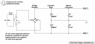
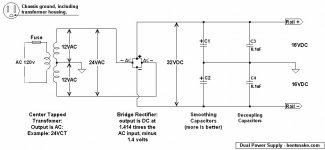
I dunno, for some reason I think the below representative schematics might be of interest. Power supplies are not complicated, even though some enjoy making them seem that way.
Meanwhile, just to chime in, the NE5532 data sheet specifies a worst-case "total supply current" of 16ma, which times 50 is 800ma, or 0.8 amp.
0.8 amp x 30 volts = 24 watts, about right for a 50 watt (50VA) transformer. (watts = volts x amps = VA)
At the same time, you want to pull 0.8 amp, the LM317 is good for 1.5 amps, well within specs.
All of which seems to mean that the people telling you that you're right are right, you had it in the first place, good to go.
Ummm...you really need 50 channels? 50? Whoa.
.
Attachments
Last edited:
The general rule is one rectifier bridge plus reservoir cap for one transformer secondary. Very experienced people may occasionally break this rule, with care. Others often think they can break this rule; they can't, and usually end up either with short circuits across half their diodes or circuit nodes which have to be at two different potentials at the same time.jammin said:Does each pair need its own bridge rectifier from the tranny? Or one high rated BR followed by paralleled smoothing caps /rectifiers.
.
<< ...it will involve about 50 dual op amps, not 50 channel mixer if thats what you meant!!? >>
I just meant a general expression of admiration and amazement. As in wow, thassa messa op amps.
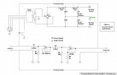
Obviously a case where small problems can become big ones. So although you didn't ask I'm going to volunteer my suggestion for a grounding method.
WAIT! The circuits posted below might (or might not) look complicated, but they're really not. The two circuits are electrically the same. It's the same circuit shown two different ways for the sake of what I hope will be clarity.
The rule being applied is to keep audio signals separated from power supply voltages and currents. This is desirable because, depending on an individual circuit and layout, resistance in conductors can create what in essence is a passive (resistor based) mixer. In this case a mixdown of audio and power occurs, which obviously will distort the audio signal.
There is no way to prevent this because all conductors have at least some resistance, so the problem is avoided by keeping audio separate from power in the first place. The two are allowed to mix only at a single ground point near the power transformer or battery(s).
Additionally, it will be seen that the power supply bypass caps are also separately routed to the single ground point. This is because these capacitors are injecting noise into ground (that's what they're for), so the intent is to minimize the mixing of noise into the audio signal.
The main capacitor bank is also routed to the single ground point because now it has to be. By now there are no other grounds to connect...
...except the decoupling capacitors located at each op amp, if used. These are not shown, but they too inject noise into ground and should be separately routed.
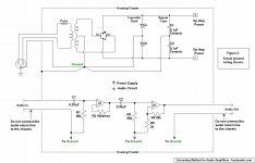
Unfortunately all this can become tedious, and in a very large circuit like yours can be ridiculously complicated. For your 50 op amps you pretty much have to fall back on some sort of ground bus arrangement. But I still suggest, at a minimum, running separate bus conductors for audio, and for power, keeping them separate until they reach the single ground point.
It might be asked, what happens to the noise at the single ground point? How is it cancelled, or where does it go? It isn't cancelled, and it doesn't go anywhere. What does happen is that it becomes insignificant.
Strictly speaking, once a voltage is created it can only be canceled by an equal voltage of opposite polarity. This does happen at the single ground point, but only at random.
The main effect is that the small noise voltages are mixed down into the relatively huge power supply voltages and currents. When this is done the relative--emphasis on relative--amplitude of the noise is reduced to several decimals. In engineering terms the noise is "swamped" by the power supply voltages and currents. It's still there, but it's relatively so small that it becomes insignificant.
I hope this might be of some interest.
.
<< ...it will involve about 50 dual op amps, not 50 channel mixer if thats what you meant!!? >>
I just meant a general expression of admiration and amazement. As in wow, thassa messa op amps.
Obviously a case where small problems can become big ones. So although you didn't ask I'm going to volunteer my suggestion for a grounding method.
WAIT! The circuits posted below might (or might not) look complicated, but they're really not. The two circuits are electrically the same. It's the same circuit shown two different ways for the sake of what I hope will be clarity.
The rule being applied is to keep audio signals separated from power supply voltages and currents. This is desirable because, depending on an individual circuit and layout, resistance in conductors can create what in essence is a passive (resistor based) mixer. In this case a mixdown of audio and power occurs, which obviously will distort the audio signal.
There is no way to prevent this because all conductors have at least some resistance, so the problem is avoided by keeping audio separate from power in the first place. The two are allowed to mix only at a single ground point near the power transformer or battery(s).
Additionally, it will be seen that the power supply bypass caps are also separately routed to the single ground point. This is because these capacitors are injecting noise into ground (that's what they're for), so the intent is to minimize the mixing of noise into the audio signal.
The main capacitor bank is also routed to the single ground point because now it has to be. By now there are no other grounds to connect...
...except the decoupling capacitors located at each op amp, if used. These are not shown, but they too inject noise into ground and should be separately routed.
Unfortunately all this can become tedious, and in a very large circuit like yours can be ridiculously complicated. For your 50 op amps you pretty much have to fall back on some sort of ground bus arrangement. But I still suggest, at a minimum, running separate bus conductors for audio, and for power, keeping them separate until they reach the single ground point.
It might be asked, what happens to the noise at the single ground point? How is it cancelled, or where does it go? It isn't cancelled, and it doesn't go anywhere. What does happen is that it becomes insignificant.
Strictly speaking, once a voltage is created it can only be canceled by an equal voltage of opposite polarity. This does happen at the single ground point, but only at random.
The main effect is that the small noise voltages are mixed down into the relatively huge power supply voltages and currents. When this is done the relative--emphasis on relative--amplitude of the noise is reduced to several decimals. In engineering terms the noise is "swamped" by the power supply voltages and currents. It's still there, but it's relatively so small that it becomes insignificant.
I hope this might be of some interest.
.
Attachments
Last edited:
Hi bentsnake! Yeah it will involve about 50 dual op amps, not 50 channel mixer if thats what you meant!!? Also thanks for the vote of confidence..
Have you considered using a single solid ground plane for all the op amps?
Then, with the op amps in a few rows, you can run the +/- rails side by side, up the middle of the packages.
- Status
- This old topic is closed. If you want to reopen this topic, contact a moderator using the "Report Post" button.
- Home
- Source & Line
- Analog Line Level
- basic power supply questions