I realise this is a DIY forum!
I have built my own active three way speakers which have worked out very well with an electronic LR4 DBX234 crossover.
By picking well behaved drivers and choosing crossover points where they are flat octaves either side, the acoustic response has remained very close to the electrical LR4 slopes.
However, I wish to improve on the PA, variable crossover (DBX234) as I feel this is holding the system back.
I have no need for a digital crossover, as my measurements demonstrate no EQ, phase, or power response problems with straight forward LR4 slopes, so I would like to go analogue.
I have looked long and hard for a simple kit - but I can't find any that provide balanced xlr in/out. Also I worry I would lack the electrical know how to build one properly.
So, can anyone point me in the direction of an 'easy' kit, or would anyone be willing to build me a 3 way LR4 balanced crossover - No level controls or variable gain required as my power amps have input sensitivity adjustments.....just a very simple balanced LR4 crossover, no more.....
Please help!")
I have built my own active three way speakers which have worked out very well with an electronic LR4 DBX234 crossover.
By picking well behaved drivers and choosing crossover points where they are flat octaves either side, the acoustic response has remained very close to the electrical LR4 slopes.
However, I wish to improve on the PA, variable crossover (DBX234) as I feel this is holding the system back.
I have no need for a digital crossover, as my measurements demonstrate no EQ, phase, or power response problems with straight forward LR4 slopes, so I would like to go analogue.
I have looked long and hard for a simple kit - but I can't find any that provide balanced xlr in/out. Also I worry I would lack the electrical know how to build one properly.
So, can anyone point me in the direction of an 'easy' kit, or would anyone be willing to build me a 3 way LR4 balanced crossover - No level controls or variable gain required as my power amps have input sensitivity adjustments.....just a very simple balanced LR4 crossover, no more.....
Please help!

Last edited:

I believe that after the XLR input and before the output, all the circuitry works in "un-balanced mode". Transformers or electronic device are used then to make it balanced.
So you need to start from the buffer, and get ready to select the jfets...
(I dunno, I've been scanning the site for years and the answer to me is : why worry with electronic crossovers? Or: I should have studied electronics first ....!)
So you need to start from the buffer, and get ready to select the jfets...
(I dunno, I've been scanning the site for years and the answer to me is : why worry with electronic crossovers? Or: I should have studied electronics first ....!)
As i said, I dunno!!
I once made some kind of low-pass filter
which used a transformer 1:1+1 and RC along the two lines
then a 5534 op amp ...as in the AN of it ( IIRC )
which worked very effectively.
Of course I'm not suggesting to double the lines to make a real balanced one.
I once made some kind of low-pass filter
which used a transformer 1:1+1 and RC along the two lines
then a 5534 op amp ...as in the AN of it ( IIRC )
which worked very effectively.
Of course I'm not suggesting to double the lines to make a real balanced one.
OK - I have given up trying to find a suitable fixed frequency crossover that isn't over £1000.
So I have order two three way crossovers and a dual symmetrical power supply from KMTech on e-bay:
NEW ! Linkwitz-Riley OPA2134 3-way active filter by KMTech assembled/tested | eBay
High Quality Dual Symmetrical Power Supply for Audio Amp UK Designed & Produced | eBay
They seem to be well made and look to be exactly what I want. I have also ordered a dual secondary 30VA 2x6V toroidal transformer from RS components to power it all:
https://uk.rs-online.com/web/p/toro...24F5448267573743D3030333050312D322D3030364B26
Being a newby to electronics it seems you just hook up the transformer to the mains (I have bought a fused, switched IEC inlet socket for this - thereby having the fuse and switch neatly dealt with in one unit: Fused Switched IEC Mains Inlet Socket Compatible With Audio Equipment Upgrades | eBay), then the two secondary neutrals to the neutral of the power supply, and each positive to one of the 6V inputs on the power supply.
I think I then wire the 6v outs of the power supply to both the crossover boards.
This seems straight forward. My issue is then making it safe. The power supply board has a grounding point, so I guess I connect this to the mains earth, and if I am using a metal case - to the chassis.
But what if I am using a plastic case?
Also what about the crossover boards - do they need grounding too, separately, because there doesn't seem to be a ground connection on them?
Thanks all - dipping my toe in the water of electronics here, and I am a little worried!
bushmeister - How are you getting on with your project?
I am considering the same modules from KMTech.
DO NOT CONNECT THE TRANSFORMER UP AS YOU HAVE SUGGESTED IT IS WRONG.
Note the transformer required is 2x6vac secondaries, but you need to connect the secondaries (output leads) so you achieve +6 0 -6 vac. (plus 6v, zero, minus 6v) for the seperate plus and minus rails on the PSU board. Like you I am no expert but came accross this on another project which was battery powered and a bit safer to cut my teeth on.
Google it to see the various ways you can connect the outputs to obtain different characteristics in terms of load/voltage. You need to understand this before progressing that's why I am not just telling you which wires to connect together.
I notice you used 30VA when the PSU board advert says use 80VA. The PSU board was originally designed for an amplifier so I am presuming the crossover boards are a smaller load.
Did KMTech recomend the 30VA rating for a pair of boards?
I would be using x4 boards in my setup so the 80VA is probably right for me but probably still overkill as I can't see these boards requiring much current.
Last edited:
Hi Qwin, don't worry I got it all working and correctly installed a few weeks after that post! Good instructions came with the boards. You are quite right, it doesn't required 30va, probably 15va is easily enough for two crossover boards.
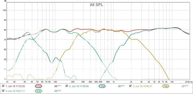
They are excellent. I have a very flat measured power response and frequency response with a very transparent sounding crossover. Appreciably better than the dbx I was using.
Don't forget in my case though i designed the speakers from scratch to yield an acoustic LR4 crossover with an electrical LR4 crossover. This required very 'flat' drivers and crossing them well within the passbands with over an octave either side of crossover point having flat frequently response. If you don't do this, my advice would be to go digital to get decent results actively.
It is always the acoustic crossover slopes that matter, so generally a standard generic active crossover like this will not give good results, unless you design the speaker to use such a slope. I have put measurements of my speakers up in another thread and the feeling was I wouldn't gain much from going digital such as the minidsp or computer crossover. I am glad as I listen to vinyl too, so keeping it all analogue is a bonus!
All this considered, the crossover boards are excellent!
That's all good to here bushmeister.
I would be using the boards on an old pair of Celestion 66 studio monitors.
The passive crossovers are simple and don’t contain notch filters or zobel networks or L-Pads. Just caps and coils, not a resistor in sight.
The drivers are flat either side of the 500 and 5000Hz crossover points.
To give you some idea, the bass driver is used in another two way system crossed at 2Khz and the mid in another crossed at 6kHz, I am using a non original tweeter that is flat way below the current crossover point.
This is what made me think they might suit a simple analogue active circuit and like you I am a keen supporter of vinyl.
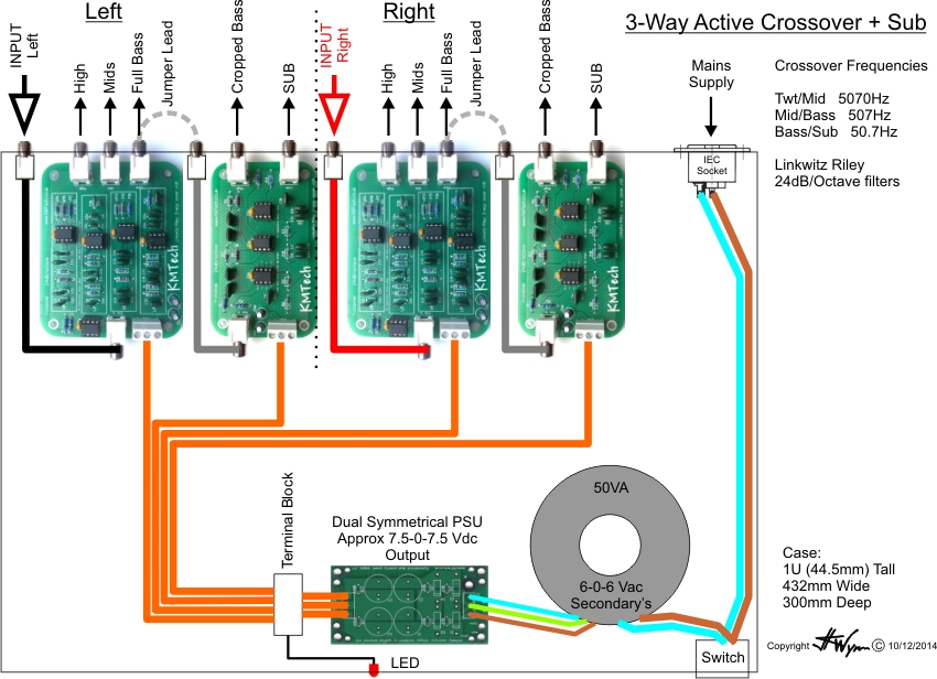
If you take the output from the bass RCA socket on the board and feed it into a further 2-Way board you can split the bass signal to get a bass/sub output that is crossed over at say 50Hz with 24dB/Octave and will integrate a sub far better than adding it to a gently rolled off main bass driver. This is normaly the case and the bass/sub end up competing for the 40-50Hz region which ends up muddy.
Just set the sub filter wide as possible and feed it the pre filtered signal.
This is something I am considering and you can set it up so you can use the basic three way output, or, by using a jumper lead, tag on the extra board to give a cropped bass plus sub output if/when needed.
I have just won a 6 channel power amp on fleebay and I’m hoping it arrives before Christmas. You can adjust individual gain on the amp to set the balance then drive it from the pre amp.
I hope to get on with the active crossover once the holidays are out of the way.
I would be using the boards on an old pair of Celestion 66 studio monitors.
The passive crossovers are simple and don’t contain notch filters or zobel networks or L-Pads. Just caps and coils, not a resistor in sight.
The drivers are flat either side of the 500 and 5000Hz crossover points.
To give you some idea, the bass driver is used in another two way system crossed at 2Khz and the mid in another crossed at 6kHz, I am using a non original tweeter that is flat way below the current crossover point.
This is what made me think they might suit a simple analogue active circuit and like you I am a keen supporter of vinyl.
If you take the output from the bass RCA socket on the board and feed it into a further 2-Way board you can split the bass signal to get a bass/sub output that is crossed over at say 50Hz with 24dB/Octave and will integrate a sub far better than adding it to a gently rolled off main bass driver. This is normaly the case and the bass/sub end up competing for the 40-50Hz region which ends up muddy.
Just set the sub filter wide as possible and feed it the pre filtered signal.
This is something I am considering and you can set it up so you can use the basic three way output, or, by using a jumper lead, tag on the extra board to give a cropped bass plus sub output if/when needed.
I have just won a 6 channel power amp on fleebay and I’m hoping it arrives before Christmas. You can adjust individual gain on the amp to set the balance then drive it from the pre amp.
I hope to get on with the active crossover once the holidays are out of the way.
Perfect!
I split the bass out of the three way crossover into my woofers on my mains and to stereo subs, then use my sub's internal crossovers. As you can see from my freq response above I cross the sub about 50hz to alleviate my 8 inch scanspeak woofers from the lowest freq. It works very well. This gives me four way speakers or three way mains with sub woofer assistance.
I am just upgrading my amps from qsc rmx850s to mc2 audio amps. I have found professional audio amps to be excellent.
Let me know if you want any help with the build!
Cheers, thanks for the offer.
When I get my 6 channel amp in the set up, a fellow enthusiast has offered to bring his miniDSP round to see how effective an active set up is with my drivers and maybe do a little experimenting with x-over points. Once these are confirmed I could order the fully built and tested boards, which are only £6 dearer than the kit. At that price its just not worth the hassle of building them yourself.
I was also wondering if parts could be upgraded, with much if any, audible improvement, better RCA sockets, OpAmps, Caps etc. If I went that route I would probably just buy the PCB's and populate myself.
You seem pretty happy with the results you are getting and KMTech are now shipping with OPA2134 if you want it. Presume you have the NE5532 versions?
EDIT: Ooops I see from post #7 you are using OPA2134.
How are you cutting off your woofers?
Last edited:
I went for an expensive toroidal transformer, the power supply unit that was supplied by kmtech - which is overengineered and designed for an amplifier, and the opa2134 op amps. I don't think it could be improved on really as it is a fairly simple circuit design and uses quality components. It has a lower noise floor than my CD player, DAC or amps and is very transparent.
If it will work with your speakers I can't see how you do better particularly for the cost.
Don't forget to ground the mains to the chassis and the power supply to the chassis too. Grounding is the most important part!! For safety and sound quality.
I cut my woofers using the 50hz high pass filter built into my qsc2450 amp, which I use for the woofers.
Last edited:
That's ok, thought that might be the case.
The seller is away till January, so will ask him then.
He is selling caps of the same make/value/voltage on his site that are 25mm tall, these look like they might be the same as those on the PSU board. That will just allow enough for safety clearances under the board tracks and above the caps plus maybe a couple of mm to spare. Fingers crossed.
I've also managed to source a 50VA 6-0-6Vac Teroidal that is 30mm tall and should fit in a 1U case.
Last edited:
Hi Bushmeister
I eventually got my crossover built, it ended up as a simple affair with just two of the KMTech 3 way boards. I did a lot of opamp rolling and ended up putting two Burson V5 discrete opamps on each board. I put them in the Buffer locations and the LP element of the band pass filter. This means each driver has only one true opamp in its path, result is much greater trancparency and detail, plus cracking bass.
I am still playing with opamp combinations for the other three positions, you can see my project here: Index
- Status
- This old topic is closed. If you want to reopen this topic, contact a moderator using the "Report Post" button.
- Home
- Source & Line
- Analog Line Level
- crossover commission/kit