Hello, I'm building a simple Electret Condenser Microphone preamp.
This will be connected to a microcontroller.
VCC will be 3.3v or 5v.
I've found some circuit, i'm now using and testing an opamp version, and a transistor version.
Here i would like to ask you questions about the transistor version.
See schematics attached.
1-----------
Can you check if what i write below is correct.
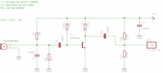
* C6, R6, R7 are there to decoulple signal and bias between VCC and GND (needed for the ADC of the microcontroller to work properly, note: the ADC read positive voltage)
* R5: load the electret mic
* C5: low pass filter
* C4: decouple signal
* R3: bias the signal to the NPN base ??? <<<
* R9: load the collector NPN
* R4: high pass filter ??? <<<
2----------
Where the gain come from? R9
3----------
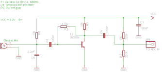
I've also found other design, where the R3 is connected between Base and Collector, like the second attachment. What's the difference?
Thank you and sorry for the newbie questions
This will be connected to a microcontroller.
VCC will be 3.3v or 5v.
I've found some circuit, i'm now using and testing an opamp version, and a transistor version.
Here i would like to ask you questions about the transistor version.
See schematics attached.
1-----------
Can you check if what i write below is correct.
* C6, R6, R7 are there to decoulple signal and bias between VCC and GND (needed for the ADC of the microcontroller to work properly, note: the ADC read positive voltage)
* R5: load the electret mic
* C5: low pass filter
* C4: decouple signal
* R3: bias the signal to the NPN base ??? <<<
* R9: load the collector NPN
* R4: high pass filter ??? <<<
2----------
Where the gain come from? R9
3----------
I've also found other design, where the R3 is connected between Base and Collector, like the second attachment. What's the difference?
Thank you and sorry for the newbie questions
Attachments

Last edited:
Your interpretation looks plausible to me in each aspect.
In the past I measured the impedance of such mics being approx 20kOhm.
This impedance is parallelled with 10k load resistor totalling 6.7Kohm.
In that case voltage gain is less than 510k/6.7k - something in the range of 60~70x.
In the past I measured the impedance of such mics being approx 20kOhm.
This impedance is parallelled with 10k load resistor totalling 6.7Kohm.
In that case voltage gain is less than 510k/6.7k - something in the range of 60~70x.
The simple circuit you posted has quite poorly defined gain figures, in other words the gain will vary tremendously depending on the type of transistor selected. It could be as low as 30 or 40 and as high as 150 to 200.
Taking the bias from the collector helps somewhat by introducing negative feedback. This helps stabilise the DC conditions and also the gain, but not really by anywhere near enough for the design to be repeatable.
Taking the bias from the collector helps somewhat by introducing negative feedback. This helps stabilise the DC conditions and also the gain, but not really by anywhere near enough for the design to be repeatable.
Tks, now i know the difference for the biasing resistor.
So, if i always use a 2n3904, and i build 10 of this board, will any of that boards have the same gain, in other works, given the same amout of noise level in the room, will the output RMS level be the same on each board?
The problem is that i would like to use this as a preamp on a rought digital Spl meter.
For a digital spl meter the Spl level expressed in dB is:
actualSPLdB = 20*log10(acutalRMSvolt/referenceRMSvolt)+referenceSPLdB
For this reason is important that the RMS output level of every board is the same.
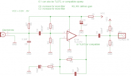
Maybe, to avoid the calibration process every time, even if is has more components involved it better to use something like the attached circuit?
Thanks!
So, if i always use a 2n3904, and i build 10 of this board, will any of that boards have the same gain, in other works, given the same amout of noise level in the room, will the output RMS level be the same on each board?
The problem is that i would like to use this as a preamp on a rought digital Spl meter.
For a digital spl meter the Spl level expressed in dB is:
actualSPLdB = 20*log10(acutalRMSvolt/referenceRMSvolt)+referenceSPLdB
For this reason is important that the RMS output level of every board is the same.
Maybe, to avoid the calibration process every time, even if is has more components involved it better to use something like the attached circuit?
Thanks!
Attachments
The opamp would give repeatable gain and would probably be more satisfactory. Noise isn't a prime consideration for your intended application.
The transistor version would never be 100% repeatable because it depends on the value of Re, the "intrinsic emitter resistance" internal to the transistor, and that will be different for each device. You could add an external emitter resistor but that would lower the overall gain, although it would make it all more repeatable.
The transistor version would never be 100% repeatable because it depends on the value of Re, the "intrinsic emitter resistance" internal to the transistor, and that will be different for each device. You could add an external emitter resistor but that would lower the overall gain, although it would make it all more repeatable.
Hi
Colin Mitchells design, is very proven and works extremely well. Here you of course do not need the tank circuit and RF antenna, but up to the 100n coupling in the schematic is certainly the best and simplest electret mic circuit I have had the pleasure of using, http://www.talkingelectronics.com/projects/Voyager/Voyager-P1.html
Note the voltage values provided, and ease of using BC 547 or PN2222 transistor.
Cheers / Chris
Last edited:
Thank you both.
I think i will test a litte the Mitchells design, which (left to the 100nF decoupling cap) is very similar to the one attached in the first post, except for values.
But for replicability i will choose the opamp version.
@Mooly: when i write "noise", i do not mean low ambient (<40db) background noise, but all type of rumors, music, people speaking and so on.
Last edited:
@Mooly: when i write "noise", i do not mean low ambient (<40db) background noise, but all type of rumors, music, people speaking and so on.
")
(I meant that white noise (hiss) isn't so much of an issue for a an SPL meter)
(I meant that white noise (hiss) isn't so much of an issue for a an SPL meter)
now i get it!
electronics without requiring the additional ±15V
Agree and add:
1) use 5V at least ; 3.3V is way too low.
Even 5V is stretching it, but at least some Op Amps can use it.
TL072 will not work there (or be so poor as to be practically useless).
TLC272 is excellent.
Just as a side note, for such utility circuits (not for "audiophile" stuff, of course) , I always used humble cheap LM358 , which is designed to work from +5V "logic" supply.
2) Op Amps are much more precise than any single transistor circuits, specially if used well within their limitations (such as , say, 10X gain).
3) I'm an Analog guy, no clue on Digital , but I guess the 220K/220K you show in all schematics is a reference voltage for the DAC.
If so, in the Op Amp version you don't need C6/R6/R7 ... pin 1 of Op Amp is already at 1/2 Vcc and is low impedance to boot
4) that said, probably you'll need to add some small gain adjustment trimmer (say 10K/22K in series with R3) because not all electret capsules will be the same.
Don't know the exact precision you need from meter to meter.
Or you might adjust it in the Software
Tell us more about your project
The opamp would give repeatable gain and would probably be more satisfactory. Noise isn't a prime consideration for your intended application.
The transistor version would never be 100% repeatable because it depends on the value of Re, the "intrinsic emitter resistance" internal to the transistor, and that will be different for each device. You could add an external emitter resistor but that would lower the overall gain, although it would make it all more repeatable.
Agree and add:
1) use 5V at least
; 3.3V is way too low.Even 5V is stretching it, but at least some Op Amps can use it.
TL072 will not work there (or be so poor as to be practically useless).
TLC272 is excellent.
Just as a side note, for such utility circuits (not for "audiophile" stuff, of course) , I always used humble cheap LM358
, which is designed to work from +5V "logic" supply.2) Op Amps are much more precise than any single transistor circuits, specially if used well within their limitations (such as , say, 10X gain).
3) I'm an Analog guy, no clue on Digital
, but I guess the 220K/220K you show in all schematics is a reference voltage for the DAC.If so, in the Op Amp version you don't need C6/R6/R7 ... pin 1 of Op Amp is already at 1/2 Vcc and is low impedance to boot
4) that said, probably you'll need to add some small gain adjustment trimmer (say 10K/22K in series with R3) because not all electret capsules will be the same.
Don't know the exact precision you need from meter to meter.
Or you might adjust it in the Software
Tell us more about your project
@JMFahey
1) thank you for suggestion, i've already use TLC272 in other design, and it works good, this time i'm checking something good but a little cheeper, i know I'm talking about cents
I will also check LM358!!
2) i get it
3) i the first two 220K (R1 and R2), bias the signal, then i need a decoupler and again two biasing resistors (C6, R6, R7), because in my test, if i do not mount that, i get the signal a little out of bias.
4) 10x gain is ok for me, i've tested with a few mics around, then i can adjust the Spl dB conversion in software.
Note 1: Given R6 connected to the ADC reference voltage of the microcontroller, If the microcontroller is powered at 3.3V and the opamp is powered with 5V (so R6 is connected to 3.3V), i experiment some problem of noise and bias (on an STM32 for example). If all is 5v (atmega as example), no problem.
Note 2: This is the first simple design i've made using a TL272, Davide Gironi: A simple Sound Pressure Level Meter (SPL) dB audio meter using AVR ATmega
For a new project, i would like to make a better design.
@Pano
Can you point me to some model? thanks!
Thank again for your help!
1) thank you for suggestion, i've already use TLC272 in other design, and it works good, this time i'm checking something good but a little cheeper, i know I'm talking about cents
I will also check LM358!!
2) i get it
3) i the first two 220K (R1 and R2), bias the signal, then i need a decoupler and again two biasing resistors (C6, R6, R7), because in my test, if i do not mount that, i get the signal a little out of bias.
4) 10x gain is ok for me, i've tested with a few mics around, then i can adjust the Spl dB conversion in software.
Note 1: Given R6 connected to the ADC reference voltage of the microcontroller, If the microcontroller is powered at 3.3V and the opamp is powered with 5V (so R6 is connected to 3.3V), i experiment some problem of noise and bias (on an STM32 for example). If all is 5v (atmega as example), no problem.
Note 2: This is the first simple design i've made using a TL272, Davide Gironi: A simple Sound Pressure Level Meter (SPL) dB audio meter using AVR ATmega
For a new project, i would like to make a better design.
@Pano
Can you point me to some model?
thanks!Thank again for your help!
Cool
Now if you already bought a dozen 3V3 ones for 1 U$ , ok, take that route.
I understand a 3V3 part can get *very* confused with a 5V signal , but a simple voltage divider can take care of that.
In fact, in another post a couple days ago, somebody compared a cheap generic electret with a more expensive calibrated one (basically by tracing the same speaker and superimposing graphs) and found that up to 5KHz they matched within 1/2 dB (incredible) and then the cheap one started rolling down a little, some -5dB at 15 KHz .
Easy to compensate with a small capacitor in series with the upper leg of the now needed voltage divider.
Anyway you must never let the Op Amp output slam against the rails.
I'd leave at least a 10dB margin, just in case.
Just curious, what practical use will your SPL meter have?
Ciao quasi Paesano
No clue on microcontrollers but if it's the same and you can use a 5V one, do it to simplify things.Note 1: Given R6 connected to the ADC reference voltage of the microcontroller, If the microcontroller is powered at 3.3V and the opamp is powered with 5V (so R6 is connected to 3.3V), i experiment some problem of noise and bias (on an STM32 for example). If all is 5v (atmega as example), no problem.
Now if you already bought a dozen 3V3 ones for 1 U$ , ok, take that route.
I understand a 3V3 part can get *very* confused with a 5V signal
, but a simple voltage divider can take care of that.In fact, in another post a couple days ago, somebody compared a cheap generic electret with a more expensive calibrated one (basically by tracing the same speaker and superimposing graphs) and found that up to 5KHz they matched within 1/2 dB (incredible) and then the cheap one started rolling down a little, some -5dB at 15 KHz .
Easy to compensate with a small capacitor in series with the upper leg of the now needed voltage divider.
Anyway you must never let the Op Amp output slam against the rails.
I'd leave at least a 10dB margin, just in case.
Just curious, what practical use will your SPL meter have?
Ciao quasi Paesano
On some microcontrollers, i can not use 5V, they works at 3.3v.
What is "strange" is that, if the opamp is powered with 5V and the micro to 3.3, even if the voltage divider is connected to 3.3v, the signal is 3.3v/2 +-8mV.
if both are connected to 5V, signal is almost on 5v/2+- 1mV.
I've not checkd it with an oscilloscope, but is what i read from the ADC of the microcontroller. Anyway.. i have to check it better!
Just to speak... as example, the STM32 ADC is 12bit, 4096step, so with a voltage of 3.3v as reference, 0 to 3.3v, no negative voltage, 3.3/4096=0.8mV precision.
Interesting comparison!
Sorry but i'm not prepared in analogic
This time, i'm reviewing the Spl meter preamp to use it in an opensource wifi ambient meter. It will have brightness, noise, humidity and temperature in the first stage.
What is "strange" is that, if the opamp is powered with 5V and the micro to 3.3, even if the voltage divider is connected to 3.3v, the signal is 3.3v/2 +-8mV.
if both are connected to 5V, signal is almost on 5v/2+- 1mV.
I've not checkd it with an oscilloscope, but is what i read from the ADC of the microcontroller. Anyway.. i have to check it better!
Just to speak... as example, the STM32 ADC is 12bit, 4096step, so with a voltage of 3.3v as reference, 0 to 3.3v, no negative voltage, 3.3/4096=0.8mV precision.
Interesting comparison!
What do you mean?Anyway you must never let the Op Amp output slam against the rails.
I'd leave at least a 10dB margin, just in case.
Sorry but i'm not prepared in analogic
This time, i'm reviewing the Spl meter preamp to use it in an opensource wifi ambient meter. It will have brightness, noise, humidity and temperature in the first stage.
Made some test.
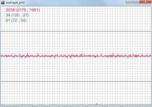
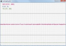
Audio board, the same you find in the first post. but with TLC272, R6 is attached to the same microcontroller supply, to bias the signal in the middle of the ADC voltage. i.e 5v/2 or 3.3v/2.
All image in silence condition.
The attached images are taken from the ADC input of the micro.
Test made:
5v audio board, 5v microcontroller (on Atmega8 ADC is 10bit)
5v audio board, 3.3v microcontroller (on STM32 ADC is 12bit)
3.3v audio board, 3.3v microcontroller (on STM32 ADC is 12bit)
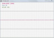
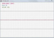
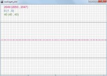
values logged, on the top left:
violet: actual raw ADC (min, max) - for 10bit the middle value should be 512, for 12 bit middle should be 4096/2
blue: RMS value
green: Spl db value
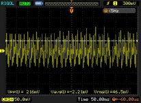
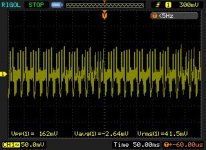
Also attached two oscilloscope screenshot of the board, one powered at 3.3v, the other powered at 5v. AC coupled.
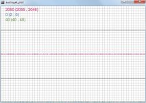
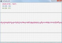
Same test on the NPN board versions, with feedback biasing resistor. Schematic attacched.
As you can see, ADC side the opamp is more noise than the npn version.
Audio board, the same you find in the first post. but with TLC272, R6 is attached to the same microcontroller supply, to bias the signal in the middle of the ADC voltage. i.e 5v/2 or 3.3v/2.
All image in silence condition.
The attached images are taken from the ADC input of the micro.
Test made:
5v audio board, 5v microcontroller (on Atmega8 ADC is 10bit)
5v audio board, 3.3v microcontroller (on STM32 ADC is 12bit)
3.3v audio board, 3.3v microcontroller (on STM32 ADC is 12bit)
values logged, on the top left:
violet: actual raw ADC (min, max) - for 10bit the middle value should be 512, for 12 bit middle should be 4096/2
blue: RMS value
green: Spl db value
Also attached two oscilloscope screenshot of the board, one powered at 3.3v, the other powered at 5v. AC coupled.
Same test on the NPN board versions, with feedback biasing resistor. Schematic attacched.
As you can see, ADC side the opamp is more noise than the npn version.
Attachments
-
 npn_feedback_bias_mic_preamp_adc.png6.7 KB · Views: 57
 -
 npn3.3vboard_3.3vmicro_12bitADC.JPG70.8 KB · Views: 41
 -
 npn5vboard_3.3vmicro_12bitADC.JPG72.2 KB · Views: 28
 -
 opamp5vscope.jpg24.3 KB · Views: 96
 -
 opamp3.3vscope.jpg22.8 KB · Views: 101
 -
 opamp3.3vboard_3.3vmicro_12bitADC.JPG71.6 KB · Views: 87
 -
 opamp5vboard_3.3vmicro_12bitADC.JPG75.3 KB · Views: 107
 -
 opamp5vboard_5vmicro_10bitADC.JPG75.2 KB · Views: 131
4.5v battery (3*1.5v) = no noise, see attachments.
attached also the 5v usb powered, or external switching supply (almost the same than usb) log.
That's why i ask for your help
But, is there a way, maybe simple, to get that same result on my powered boards?
Or have i to use the 3.3v powering?
thanks!
attached also the 5v usb powered, or external switching supply (almost the same than usb) log.
That's why i ask for your help
But, is there a way, maybe simple, to get that same result on my powered boards?
Or have i to use the 3.3v powering?
thanks!
Attachments
Measurements can be a bit of a problem interpreting the results. So its quiet on battery. I would suggest as a test keeping it battery powered but adding just the ground connection from battery powered preamp to USB. See if the noise alters. If it does you have a measurement interaction of some sort. If it doesn't then still keeping it battery powered connect the preamp output to the required input and again see if the noise alters. If it does then perhaps there is hash/noise feeding back from the input of the PC.
Have you scoped the input to the PC on its own with no preamp connected.
Have you scoped the input to the PC on its own with no preamp connected.
Connected to the scope, and powered with battery, the opamp give me really slow noise.
Tested powering the opamp with the battery, and a ground cable to USB. And even trying with a switching supply. More or less the same results of the figure 2 above, the one with noise.
That is not a PC input, is an ADC input of a microcontroller, that do ADC conversion, and send data to UART.
I think i have to test the 12bit ADC, setting is reference voltage to 5v, and powering the board with 5v. Or, for this hardware, i will power the opamp with 3.3v (same voltage of the microcontroller), or use the NPN version. This will prevent that noise.
- Status
- This old topic is closed. If you want to reopen this topic, contact a moderator using the "Report Post" button.
- Home
- Live Sound
- Instruments and Amps
- Electret Condenser Microphone preamp analysis