I have a classic car. An OEM tuner/tape player with balanced outputs and a JL audio amp with balanced inputs. If I have the volume loud when I park the car, the next time I start up, BLAM loud music! Car stereo has a volume up/down toggle. I am looking for a circuit that I can install between the HU and the amp that will take the volume to minimum and slowly increase it (30 secs or so) when power is applied. On the other hand, In the HU there is a small analog control signal of .2-3 volts that feeds the volume chip in the radio. If I had a small circuit that would buffer that to zero at turn off and slowly increase it to the input voltage that would work too. Working with car stereo only gives me +12vdc to work with so no dual voltage IC's. I have been searching for two weeks now. Any ideas O wise ones?
Just a quick idea, but you would have to figure the details ")
Your control voltage could be fed into an R/C network the time constant of which determines the rise of the control voltage. How that might work would depend on the input impedance of the volume chip and the drive ability of the chip feeding it all. You tie the cap to the switched 12v rail in the radio via a diode so that turning the radio off discharges the cap instantly ready for next time.
Finally you add a bypass across the resistor in the R/C network so that after your 30 seconds have elapsed the volume can be operated normally. Without that and the volume would be slow to respond. That could be a single JFET or CMOS switch.
If the drive ability/impedances of the chip don't allow an R/C network of reasonable values then add a buffer using a single suitable opamp (FET or CMOS that works down to zero volts)
I have been thinking about the same thing for HiFi
I recently got a harman-kardon citation eleven from a well known auction site. The harman-kardon citation eleven has exactly this feature. This valve like increase of volume slowly is a very nice feature not common in transistor circuits.
The harman-kardon citation eleven is currently unusable as it is. The capacitors have never been replace and are probably 40 years old and some of them have already or are close to failing. I gave it a short test but wont be using this preamp until I have completed replacing all the electrolytic capacitors. The build quality of this kit is so high that I expect I will rebuilt it very soon. (Have ordered some calipers as I am tied of measuring these things with a ruler or a tape measure)
The original service manual is available.on HiFi Engine
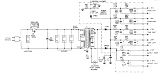
I have cut out the appropriate sections of the schematic and included as attachments.
Q507, Q507, Q509, Q5011 are 2N3417
Q506, Q508, Q5010 are harman-kardon special parts.
I am thinking I will return the unit to better than the original specs but am thinking that I might well add this switch on delay to my own home designed preamp.
Do people have any suggestions for replacing the Q506, Q508, Q5010 FETs?
Do people think that this form of turn on delay will degrade the sound?
Do people think that this approach would make a good source selector in a preamp.
I recently destroyed a Quad ESl 63 by switching my preamp to select input from an audio item that was broken and clipping, so I would like a turn on "warm up" for each source.
Finally can we do this all on 12 V for the use for the original poster?
I recently got a harman-kardon citation eleven from a well known auction site. The harman-kardon citation eleven has exactly this feature. This valve like increase of volume slowly is a very nice feature not common in transistor circuits.
The harman-kardon citation eleven is currently unusable as it is. The capacitors have never been replace and are probably 40 years old and some of them have already or are close to failing. I gave it a short test but wont be using this preamp until I have completed replacing all the electrolytic capacitors. The build quality of this kit is so high that I expect I will rebuilt it very soon. (Have ordered some calipers as I am tied of measuring these things with a ruler or a tape measure)
The original service manual is available.on HiFi Engine
I have cut out the appropriate sections of the schematic and included as attachments.
Q507, Q507, Q509, Q5011 are 2N3417
Q506, Q508, Q5010 are harman-kardon special parts.
I am thinking I will return the unit to better than the original specs but am thinking that I might well add this switch on delay to my own home designed preamp.
Do people have any suggestions for replacing the Q506, Q508, Q5010 FETs?
Do people think that this form of turn on delay will degrade the sound?
Do people think that this approach would make a good source selector in a preamp.
I recently destroyed a Quad ESl 63 by switching my preamp to select input from an audio item that was broken and clipping, so I would like a turn on "warm up" for each source.
Finally can we do this all on 12 V for the use for the original poster?
Attachments
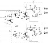
It might be possible but you would need to experiment and build a prototype. This uses JFET's as a voltage controlled resistance shunting the audio. The OP needs to limit the rate of rise of an "up to" 3 volts DC control voltage.
(The JFET's only degrade the audio during the on to off phase. Normally they are biased off)
(The JFET's only degrade the audio during the on to off phase. Normally they are biased off)
I think the best way would be to use a LDR (light-dependant resistor, I modeled a Silonex) in a voltage divider on each channel. Unfortunately, the circuit isn't very simple due to the non-linearity of the LDR turn-on and the need for a logarithmic volume increase. In simulation, the following circuit gives a ramp-up to half volume of about 7 seconds, 95% volume in about 15 seconds, and 99% volume in about two minutes.
Of note: D1 and D2 are the LDR LEDs. D3 is a 12v zener. D4, D5, and D6 are standard red LEDs.
Of note: D1 and D2 are the LDR LEDs. D3 is a 12v zener. D4, D5, and D6 are standard red LEDs.
An externally hosted image should be here but it was not working when we last tested it.
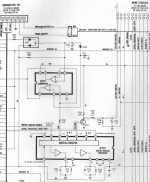
Thanks for all the varying and informative replies. I am going to try and post a small pic of the circuit from the service manual. Q731 is the circuit in question. I am not sure if the data is reloaded to the D/A at turn on, or if it's loaded once at each volume change and kept until changed again or power (battery) is removed.
Attachments

What I posted above is exactly what you need. The voltage symbol on the left is for the power from the car - it's usually above 12v, somewhere around 13 to 14. The "In" is for the signal in, the out is for out, and the signal ground is the signal ground. I only showed one channel for clarity. If you just want to work with the control signal, give me a few hours to come up with something, it should be pretty straightforward.
I can't tell what's going on in the schematic, but in your buffer, change R1 to 22K and add a 1000uF capacitor in parallel. Change the R2 above that (you have two R2s) to 50K. Get rid of the input and output capacitors and there's no "in" signal, just the out which will take about 30 seconds to ramp up to 2.6v and 60 seconds to get to 3v.
On the car stereo schematic, Pin 3 of the D/A converter is fed directly to the base of the transistor. The output of that tranny goes off the print to a stereo chip where it controls the output of the preamp. Fenris, I was hoping to be able to have some sort of ramping gain type buffer. If I just put the "ramp to 3 volts" circuit in the radio, it will stay at whatever volume 3 volts is and I won't be able to change it. Any way to make the audio buffer start out at say -10% output and rise to unity gain after 30 seconds or so? I could build a couple and place them between the HU and the amp.
Looking at the circuit and the output from the chip could be a PWM control signal (pulses) that are integrated by the R/C network on the emitter. It also looks odd that the two resistors are specified as 1% tolerance... as if it could be critical to the absolute range of control the circuit offers.
Buffer the output with a rail-to-rail opamp (OPA171, OPA7321, TLE2071 are some examples) set as a unity gain buffer. Use a 555 to make a timer circuit and attach to a relay. At the opamp output, put a 10K resistor. Put a capacitor (330uF or so) to ground after that. Wire it so that the capacitor is disconnected by the relay after 30 seconds.
Reading the circuit description in the manual leads me to believe is is a straight DC level.Looking at the circuit and the output from the chip could be a PWM control signal (pulses) that are integrated by the R/C network on the emitter. It also looks odd that the two resistors are specified as 1% tolerance... as if it could be critical to the absolute range of control the circuit offers.
Reading the circuit description in the manual leads me to believe is is a straight DC level.
Across the cap, yes. The control voltage from the chip looks to me like it would PWM. Put a scope on it and have a look see
I recently got a harman-kardon citation eleven from a well known auction site. The harman-kardon citation eleven has exactly this feature. This valve like increase of volume slowly is a very nice feature not common in transistor circuits.
After replacing all the electrolytic capacitors this preamp is now a very nice very usable item.
The original service manual is available.on HiFi Engine
It is not significant in my opinion.Do people think that this form of turn on delay will degrade the sound?
I think this might make a very nice source selector.Do people think that this approach would make a good source selector in a preamp.
- Status
- This old topic is closed. If you want to reopen this topic, contact a moderator using the "Report Post" button.
- Home
- Source & Line
- Analog Line Level
- slow audio increase at turn on?