I would like to continue my thread about the Apple Remote here since it is no longer really about just the Apple Remote anymore.
Background:
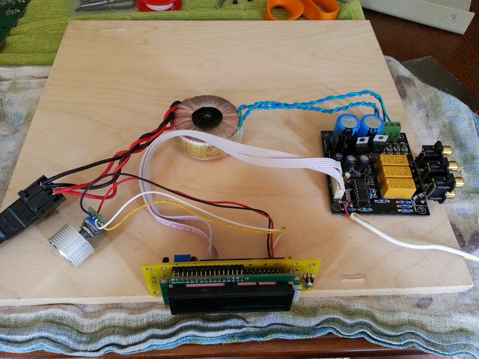
I purchased an ebay PGA2311 kit to play with. Recently I decided that I want to integrate this into an existing Aikido preamp where I wanted to add remote controlled volume and input switching.
Enter the Arudino Uno
I want to turn this kit:
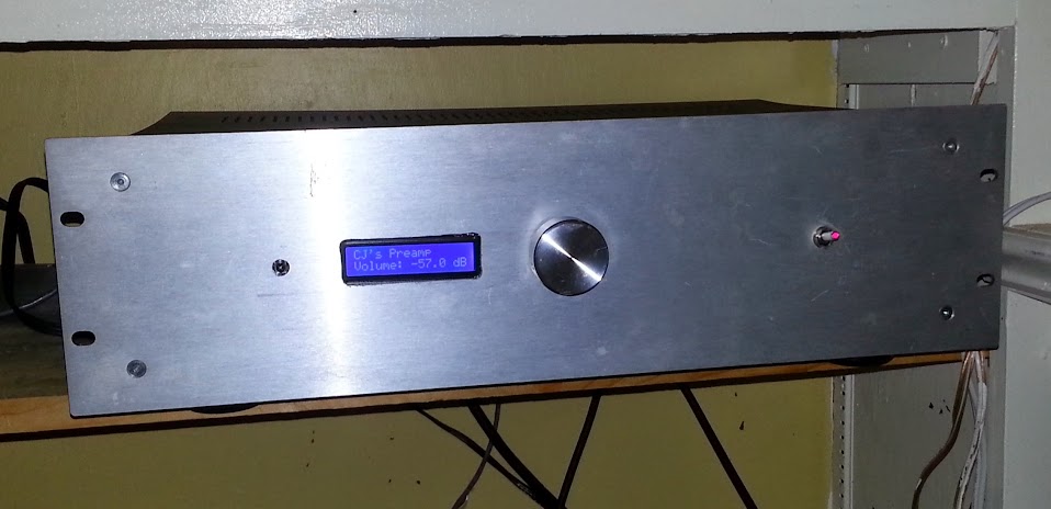
Into this:
I have been following numerous threads about this and will keep my progress updated here.
I am an Arduino novice - maybe not even a novice so I appreciate any help with coding that may come up.
Pasted below is a response from ElectoNick Thanks!!! It think this is a good starting point to begin the Arduino sketch.
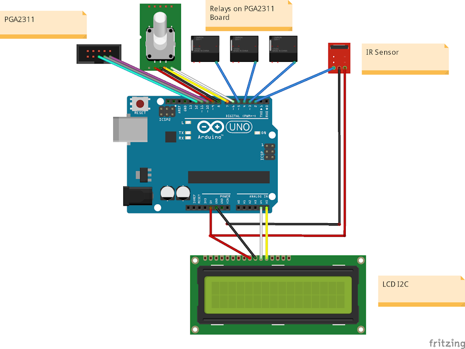
Well, i would do this :
- put parallel LCD on analog ports (no need for a new lcd)
- put rotary encoder on interupts (you want to use them !)
- put PGA2311 on some digital lines, same as IR and relays.
eg on Arduino :
0 = RotaryA (rotary_encoder)
1 = RotaryB (rotary_encoder)
2 = pushbutton (rotary_encoder)
3 = Selection Pin (spi)
4 = MOSI (spi)
5 = MISO (spi)
6 = Clock (spi)
7 = IR_receiver
8 = output for relay_A
9 = output for relay_B
10 = output for relay_C
11 = n.c.
12 = n.c.
13 = n.c.
14 = RS (lcd)
15 = enable display (lcd)
16 = D4 (lcd)
17 = D5 (lcd)
18 = D6 (lcd)
19 = D7 (lcd)
GND = R/W (lcd)
Background:
I purchased an ebay PGA2311 kit to play with. Recently I decided that I want to integrate this into an existing Aikido preamp where I wanted to add remote controlled volume and input switching.
Enter the Arudino Uno
I want to turn this kit:
Into this:
I have been following numerous threads about this and will keep my progress updated here.
I am an Arduino novice - maybe not even a novice so I appreciate any help with coding that may come up.
Pasted below is a response from ElectoNick Thanks!!! It think this is a good starting point to begin the Arduino sketch.
Well, i would do this :
- put parallel LCD on analog ports (no need for a new lcd)
- put rotary encoder on interupts (you want to use them !)
- put PGA2311 on some digital lines, same as IR and relays.
eg on Arduino :
0 = RotaryA (rotary_encoder)
1 = RotaryB (rotary_encoder)
2 = pushbutton (rotary_encoder)
3 = Selection Pin (spi)
4 = MOSI (spi)
5 = MISO (spi)
6 = Clock (spi)
7 = IR_receiver
8 = output for relay_A
9 = output for relay_B
10 = output for relay_C
11 = n.c.
12 = n.c.
13 = n.c.
14 = RS (lcd)
15 = enable display (lcd)
16 = D4 (lcd)
17 = D5 (lcd)
18 = D6 (lcd)
19 = D7 (lcd)
GND = R/W (lcd)
Good info here on using the IR receiver functions and getting the right remote codes
Then on to here to see about getting the PGA running and working volume
Last will be to be able to switch inputs. Been looking a lot at MaxW's thread HERE
More good info HERE for triggering relays
Then on to here to see about getting the PGA running and working volume
Last will be to be able to switch inputs. Been looking a lot at MaxW's thread HERE
More good info HERE for triggering relays
OK...ran a IR receive decoder on the Uno with the apple remote for fun.
Unfortunately based upon what I have read I am not seeing the same code or code format that others have reported.
UP 77E15004
DOWN 77E13004
LEFT 77E19004
RIGHT 77E16004
CENTER 77E13A04 77E1A004
MENU 77E1C004
PLAY/PAUSE 77E1FA04 77E1A004
I dont think I have seen these codes called out in any "code" that I have seen related to the apple remote.
Sorry for the noob questions...
Another update:
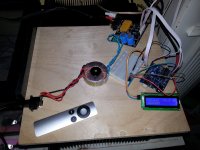
I have inserted the PGA2311 into doing full preamp duties for test.
Apple remote works for volume up and down and I tried a version that switches the inputs but no go.
Any advice or suggestions on how to code the arduino to switch relays would be appreciated.
I have inserted the PGA2311 into doing full preamp duties for test.
Apple remote works for volume up and down and I tried a version that switches the inputs but no go.
Any advice or suggestions on how to code the arduino to switch relays would be appreciated.
Attachments

I love the look of your remote control. Are those available somewhere? I wanted to use Arduino to make remote control for a stereo preamp I built but decided writing code is over my head. It would probably take more time than I can afford right now.Bench setup...
Funny...the pga2311 is a nice sounding chip...I've never run it alone as a preamp.
Code:
#include <IRremote.h>

int RECV_PIN = 6;
int relay1 = 2;
int relay2 = 3;
int relay3 = 4;

int on = 0;
int on1 = 0;
int on2 = 0;
int on3 = 0;

IRrecv irrecv(RECV_PIN);
decode_results results;

void setup()
{
  pinMode(relay3, OUTPUT);
  pinMode(relay2, OUTPUT);
  pinMode(relay1, OUTPUT);
  pinMode(13, OUTPUT);
  irrecv.enableIRIn(); // Start the receiver
}

unsigned long last = millis();

void loop() {
  if (irrecv.decode(&results))
  {
    if (results.value == 2011254788)
    { // Remote Control Power Code
      // If it's been at least 1/4 second since the last
      // IR received, toggle the relay
      if (millis() - last > 250)
      {
        on = !on;
        digitalWrite(relay1, on ? HIGH : LOW);
      }
      last = millis();
    }

    else if (results.value == 2011258884)
    {
      if (millis() - last > 250)
      {
        on1 = !on1;
        digitalWrite(relay2, on1 ? HIGH : LOW);
      }
      last = millis();
    }

    else if (results.value == 2011246596)
    {
      if (millis() - last > 250)
      {
        on2 = !on2;
        digitalWrite(relay3, on2 ? HIGH : LOW);
      }
      last = millis();

    }

    irrecv.resume(); // Receive the next value
  }
}
OK I tried this bit of code out with the addition of my apple remote up, right, and down code and I was successfully able to switch between relays, but what I want to do is scroll through the inputs only using the left and right buttons on the remote.
Getting closer, any advice or suggestions on tweaking this bit of code is appreciated.
Code:
UP	 77E15004 	2011254788
DOWN	 77E13004	2011246596
LEFT 	77E19004	2011271172
RIGHT 	77E16004	2011258884
CENTER	 77E13A04 77E1A004	2011249156
MENU 	77E1C004	2011283460
PLAY/PAUSE	 77E1FA04 77E1A004	2011298308
OK making a little more progress...
Working:
Still need to fix:
Here is the latest functioning code:
Working:
- So far I changed the welcome message
- I got rid of the volume bar thing that didnt display right
- On the remote the left button toggles the input 1 on/off
- The right button toggles input 2 on/off
- The top button is volume up
- Bottom button is volume down
Still need to fix:
- On the display I tried to get it to display which input is active to the right of the startup message. The input shows and stays on until you adjust the volume and it goes away.
- The ability to scroll through the inputs just by pressing left or right buttons
- Add a mute function by pressing play/pause - just need to assign function to button and pin on arduino board
- Need to add encoder
Here is the latest functioning code:
Code:
/*
 Arduino pins:
 - digital pin 13 (SCK) = SPI SCLK (PGA2311 pin 6)
 - digital pin 12 (MISO) = not used
 - digital pin 11* (MOSI) = SPI SDI/MOSI (PGA2311 pin 3)
 - digital pin 10* (SS) = SPI \CS (PGA2311 pin 2)
 - digital pin 6* = IR receiver data
 - digital pin 1 = not connected
 - digital pin 0 = not connected
 * is a PWM pin

/*-----( Import needed libraries )-----*/
#include <Wire.h>  // Comes with Arduino IDE
// Get the LCD I2C Library here:
// https://bitbucket.org/fmalpartida/new-liquidcrystal/downloads
// Move any other LCD libraries to another folder or delete them
// See Library "Docs" folder for possible commands etc.
#include <LiquidCrystal_I2C.h>
#include <IRremote.h>
#include <stdlib.h>
#include <SPI.h>

/*-----( Declare Constants )-----*/
/*-----( Declare objects )-----*/
// set the LCD address to 0x27 for a 20 chars 4 line display
// Set the pins on the I2C chip used for LCD connections:
//                    addr, en,rw,rs,d4,d5,d6,d7,bl,blpol
LiquidCrystal_I2C lcd(0x27, 2, 1, 0, 4, 5, 6, 7, 3, POSITIVE);  // Set the LCD I2C address

/*-----( Declare Constants )-----*/
#define RELAY_ON 0
#define RELAY_OFF 1
/*-----( Declare objects )-----*/
/*-----( Declare Variables )-----*/
#define Relay_1  2  // Arduino Digital I/O pin number
#define Relay_2  3
#define Relay_3  4

/*IR detector data=pin 6

* PGA2311 gain:
N = 1 to 255
* Gain (dB) = 31.5-[0.5*(255-N)]

* SPI interface:
* /CS (pin 2)
* SCLK (pin 6)
* SDI (pin 3)
* SDO (pin 7)

*/

const int slaveSelectPin = 10;
int RECV_PIN = 6;
IRrecv irrecv(RECV_PIN);
decode_results results;
String lastIRoperation;
int relay1 = 2;
int relay2 = 3;

int on = 0;
int on1 = 0;
int on2 = 0;

char cGain[17];
String gain;
char icGain[6];
float iGain = -95.5;
float nGain = 1;


void setup() {
  Serial.begin(9600);  // Used to type in characters

  lcd.begin(16,2);   // initialize the lcd for 16 chars 2 lines, turn on backlight
  lcd.write("CJ's Preamp ");

  irrecv.enableIRIn();

  pinMode(slaveSelectPin, OUTPUT);
  SPI.begin();

  //-------( Initialize Pins so relays are inactive at reset)----
  digitalWrite(Relay_1, RELAY_ON);
  digitalWrite(Relay_2, RELAY_OFF);

//---( THEN set pins as outputs )----

  pinMode(relay2, OUTPUT);
  pinMode(relay1, OUTPUT);

  delay(4000); //Check that all relays are inactive at Reset


}
int VolumeUp() {
    if (nGain < 255) {
      nGain = nGain + 1;
      setGain(nGain);
      setVolumeBar(nGain);
    }
    else {
      lcd.setCursor(0, 0);
      lcd.write("Maximum Reached");
      delay(500);
    }
}
int VolumeDown() {
    if (nGain > 1) {
      nGain = nGain - 1;
      setGain(nGain);
      setVolumeBar(nGain);
    }
    else {
      lcd.setCursor(0,0);
      lcd.write("Minimum Reached ");
      delay(500);
    }
}

void setGain(int nGain) {
  digitalWrite(slaveSelectPin,LOW);
  SPI.transfer(nGain);  // right channel
  SPI.transfer(nGain);  // left channel
  digitalWrite(slaveSelectPin,HIGH);
}

void setVolumeBar(int nGain) {
  // convert gain to a decibal string, and write to the lcd
  iGain = 31.5 - 0.5*(255 - float(nGain));
  gain.toCharArray(icGain, 6);
  dtostrf(iGain,4,1,icGain);
  gain = String(icGain);
  lcd.clear();
  lcd.write("CJ's Preamp ");
  ("Volume: " + gain + " dB").toCharArray(cGain,17);
  lcd.setCursor(0, 1);  //first line
  lcd.write(cGain);
  // write the volume bar
    }


unsigned long last = millis();

void loop() {
  // Decode the IR if recieved
  if (irrecv.decode(&results)) {
    if(results.value == 2011254788) {
      lastIRoperation = "volumeUp";
      VolumeUp();
    }
    if(results.value == 2011246596) {
      lastIRoperation = "volumeDown";
      VolumeDown();
    }
       if (results.value == 2011271172)
    { // Remote Control Power Code
      // If it's been at least 1/4 second since the last
      // IR received, toggle the relay
      if (millis() - last > 250)
      {
        on = !on;
        digitalWrite(relay1, on ? HIGH : LOW);
          lcd.setCursor(13,0); //Start at character 13 on line 0
          lcd.print("IN1");
      }
      last = millis();
    }

    else if (results.value == 2011258884)
    {
      if (millis() - last > 250)
      {
        on1 = !on1;
        digitalWrite(relay2, on1 ? HIGH : LOW);
          lcd.setCursor(13,0); //Start at character 13 on line 0
          lcd.print("IN2");
      }
      last = millis();
    }
    if(results.value == 4294967295) {
      if (lastIRoperation == "volumeUp") { VolumeUp(); }
      if (lastIRoperation == "volumeDown") { VolumeDown(); }
    }
    irrecv.resume(); // Receive the next value
  }

}It occurred to me that I'd rather use my smart phone for a remote for my stereo than a separate dedicated remote. Now days virtually everyone has a smartphone by their side. Just need to find someone who can write the application, and create the receiving end interface. I'd want input selection, volume, mute, a few tone options, maybe an external processor in/out option and that's about it. Any thoughts?

Yes. Thankyou.
Maybe this blog from my friend FarmTech will be helpful for you:
http://blog.royalsystems.dk/#post26
http://blog.royalsystems.dk/#post26
- Home
- Source & Line
- Analog Line Level
- Another Modified PGA2311 kit with Arduino for volume control and input selection