Arduino input switching with PGA2311 volume control...revised apple remote thread
I can solder and basic assembly/construction skills. I understand tube and simple solid state schematics but this is new to me.
I have seen some pga2311 modules controlled by the apple remote but I want to understand either how to make that work or if there is a module available that works with the apple remote out of the box.
I know that arduino might be an option but I know nothing about it.
I am OK learning and if some type of programmer can be had for cheap and is simple to do I am willing to do that.
I have a pga2311 already but I don't mind spending a few dollars on a new module if necessary.
Last edited:
After searching for a few hours it looks possible to take my existing eBay pga2311 kit and with the addition of something like an arduino uno I might accomplish what I want.
Basically I would like to add remote switching input and volume control to an existing aikido preamp using the apple remote.
The unit works as is but only with the crappy remote that came with it.
http://www.diyaudio.com/forums/analog-line-level/173270-my-preamp-project-arduino-i2c-relay-selector-attenuator-tube-stage.html
Something very similar to what Max has been working on here. Suggestions on how to integrate an arduino into my existing pga2311?
Here is what I have now...I am thinking that the board in back of the LCD needs to be removed and the arduino would replace its functionality. I would probably need a new pot/encoder right? And potentially a new IR receiver. I have it working downstream from my Aikido now and it is silent and all functions work as I want except for the remote.
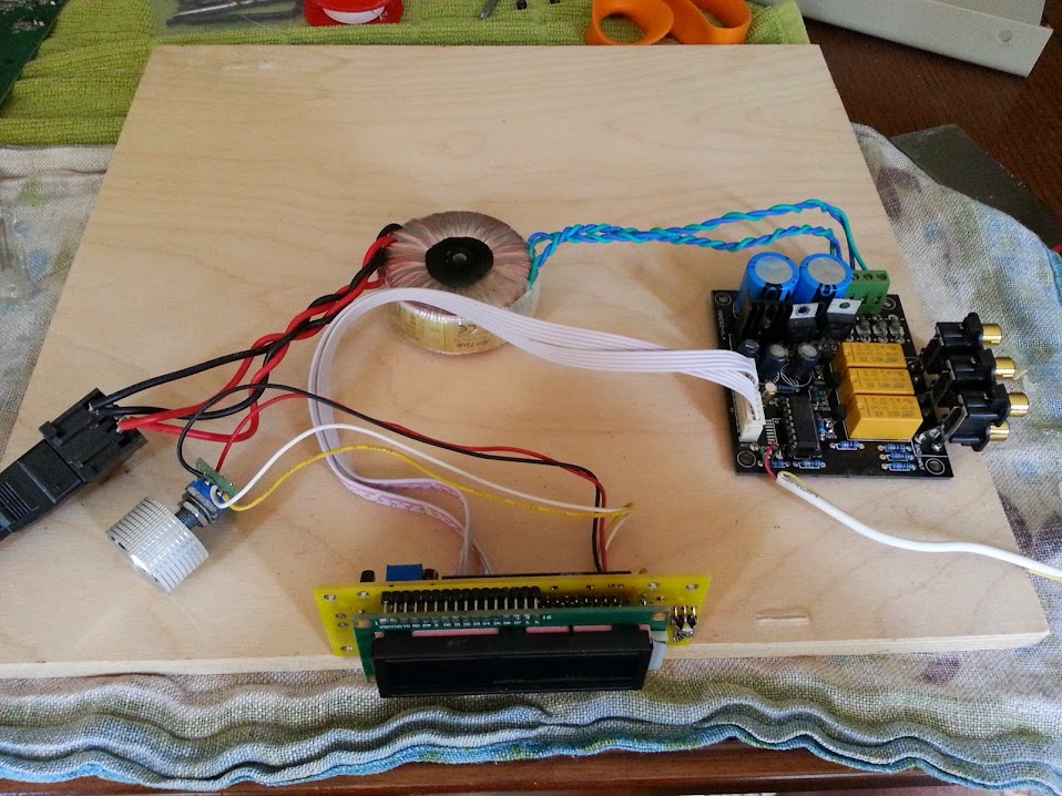
I don't think you need to replace anything more than the CPU-board.
The encoder and IR receiver are re-usable.
All it takes is som creative programming with an Arduino.
ps : maybe the wavelength of the IR-receiver could be an isue.
Yes, from what I understand the Arduino will need to go in between the screen module and the PGA board. Beyond that I need to learn more.
OK I am beginning to understand what I need to do.
So I think I have the apple remote issue handled with the Arduino. I also think I am good with the volume control piece.
What I am missing though is I am in need of some advice on how to handle the input switching using the Arduino. Any thoughts or ideas on how to proceed here is appreciated.
So I think I have the apple remote issue handled with the Arduino. I also think I am good with the volume control piece.
What I am missing though is I am in need of some advice on how to handle the input switching using the Arduino. Any thoughts or ideas on how to proceed here is appreciated.
Find out how the original controller works :
- how are the relays controlled (SPI/I2C/direct)
- how is the volume chip controlled (SPI / I2C)
- how is the LCD controlled (i guess parallel 4 bit)
There are loads of examples how to do this, you're not the first one.
So don't try to reinvent the wheel, start with some working (arduino) sketches and work from there.
This is what i'm also trying....")
- how are the relays controlled (SPI/I2C/direct)
- how is the volume chip controlled (SPI / I2C)
- how is the LCD controlled (i guess parallel 4 bit)
There are loads of examples how to do this, you're not the first one.
So don't try to reinvent the wheel, start with some working (arduino) sketches and work from there.
This is what i'm also trying....
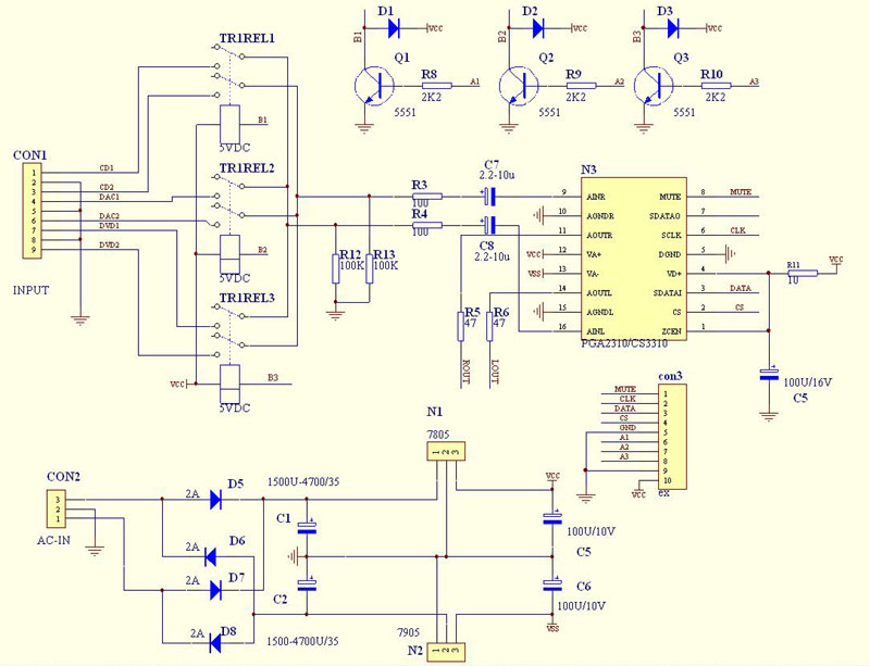
Attached are the schematic of the PGA3211 system that I have.
The relays are controlled by the controller IC. Best I can tell the signal comes from pins 36, 37, or 38 and sent to the corresponding 2n5551 then to its relay to make the connection.
So what I need to do is have the Arduino take the chore of this activity.
So basically I want the Arduino to completely replace the controller that is mounted behind the LCD.
With it I want the Arduino to send info to the LCD, Control the PGA2311 volume, and allow switching of inputs using the apple remote.
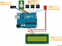
I received my Arduino Uno and started playing with Fritzing.
I figured that in order to have enough pins to do what I want I needed a new LCD that was set up for I2C so it only needs 4 pins.
Since I am not using an IC for switching inputs I set aside 3 pins for that duty.
I have accounted for an IR receiver as well as a rotary encoder - using my existing one.
Now I have to learn how to code this bugger and figure out which pins I need to assign for what duty.
Attachments
Well, i would do this :
- put parallel LCD on analog ports (no need for a new lcd)
- put rotary encoder on interupts (you want to use them !)
- put PGA2311 on some digital lines, same as IR and relays.
eg on Arduino :
0 = RotaryA (rotary_encoder)
1 = RotaryB (rotary_encoder)
2 = pushbutton (rotary_encoder)
3 = Selection Pin (spi)
4 = MOSI (spi)
5 = MISO (spi)
6 = Clock (spi)
7 = IR_receiver
8 = output for relay_A
9 = output for relay_B
10 = output for relay_C
11 = n.c.
12 = n.c.
13 = n.c.
14 = RS (lcd)
15 = enable display (lcd)
16 = D4 (lcd)
17 = D5 (lcd)
18 = D6 (lcd)
19 = D7 (lcd)
GND = R/W (lcd)
pins 14 to 19 are the analog ports, but you can call them also A0-A5.
I've tried the LCD on analog ports, works perfect.
I realise it's a bit difficult in the beginning, but you can built this and then go on tweaking your software like a pro (this will take some time, i know.....)
Regards,
Nick
- put parallel LCD on analog ports (no need for a new lcd)
- put rotary encoder on interupts (you want to use them !)
- put PGA2311 on some digital lines, same as IR and relays.
eg on Arduino :
0 = RotaryA (rotary_encoder)
1 = RotaryB (rotary_encoder)
2 = pushbutton (rotary_encoder)
3 = Selection Pin (spi)
4 = MOSI (spi)
5 = MISO (spi)
6 = Clock (spi)
7 = IR_receiver
8 = output for relay_A
9 = output for relay_B
10 = output for relay_C
11 = n.c.
12 = n.c.
13 = n.c.
14 = RS (lcd)
15 = enable display (lcd)
16 = D4 (lcd)
17 = D5 (lcd)
18 = D6 (lcd)
19 = D7 (lcd)
GND = R/W (lcd)
pins 14 to 19 are the analog ports, but you can call them also A0-A5.
I've tried the LCD on analog ports, works perfect.
I realise it's a bit difficult in the beginning, but you can built this and then go on tweaking your software like a pro (this will take some time, i know.....
)Regards,
Nick
Last edited:
MODS - we can close this thread - I will continue with my new thread which is more relevant to the project objective.
I have an old ARDUINO implementation of an APPLE remote in some old Wolfson Thread - Still using the DAC but without the ARDUINO
And I surely not want you to be able to clear the info you got from others that can be very useful... Well, if you wan't to Ok, go ahead - I've copied the lot
Regards
Last edited:
- Status
- This old topic is closed. If you want to reopen this topic, contact a moderator using the "Report Post" button.
- Home
- Source & Line
- Analog Line Level
- is there an off the shelf preamp module that works with the apple remote?