Hello.
I was hoping for some help with a 2 pole low pass filter/attenuator.
I need to provide a low pass input to a woofer amp, but also to attenuate the
signal level a bit to help match with the midrange(less sensitive).
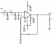
Here is the configuration I was hoping to use, with the amplifier input impedance at 20k ohms.
I calculate a second order low pass at around 400Hz, but about how much attenuation will layout this give,(-6db)??
TIA
-Chas
I was hoping for some help with a 2 pole low pass filter/attenuator.
I need to provide a low pass input to a woofer amp, but also to attenuate the
signal level a bit to help match with the midrange(less sensitive).
Here is the configuration I was hoping to use, with the amplifier input impedance at 20k ohms.
I calculate a second order low pass at around 400Hz, but about how much attenuation will layout this give,(-6db)??
TIA
-Chas
Attachments
Hi,
Thats not a two pole filter. Its a cascaded passive 1st order
buffered with a gain stage you can set to any gain you like.
The input could easily be attached to a 20K volume pot.
rgds, sreten.
Checkout TinaTi :
SPICE-Based Analog Simulation Program - TINA-TI - TI Software Folder
Thats not a two pole filter. Its a cascaded passive 1st order
buffered with a gain stage you can set to any gain you like.
The input could easily be attached to a 20K volume pot.
rgds, sreten.
Checkout TinaTi :
SPICE-Based Analog Simulation Program - TINA-TI - TI Software Folder
Last edited:
OK. Thanks.
So, what characteristics does a cascaded passive first order filter have,
compared to a passive second order filter?
BTW the filter is being attached to the input of a TK2050 based power amplifier(the gain diagram was lifted from somewhere else for illustration purposes).
I read this on a Google search for 2nd order filter:
>Thats not a two pole filter. Its a cascaded passive 1st order ...<
So, what characteristics does a cascaded passive first order filter have,
compared to a passive second order filter?
BTW the filter is being attached to the input of a TK2050 based power amplifier(the gain diagram was lifted from somewhere else for illustration purposes).
I read this on a Google search for 2nd order filter:
-Chas...a first-order low pass filter can be converted into a second-order type by simply adding an additional RC network to it and the more RC stages we add the higher becomes the order of the filter...
>Thats not a two pole filter. Its a cascaded passive 1st order ...<
Last edited:
OK. Thanks.
So, what characteristics does a cascaded passive first order filter have,
compared to a passive second order filter?>Thats not a two pole filter. Its a cascaded passive 1st order ...<
This is indeed a second order filter, as the ultimate rolloff is 12dB/octave, but the response at the corner is 6dB down. A second order active filter can be designed with more useful behavior.
Hi,
Your all talking nonsense. Its a poorly cascaded 1st order
that hasn't a hope in hell of replicating a second order
or being barely different to a simple RC first order.
rgds, sreten.
Properly cascaded 1st order filters can approximate
very low Q higher order fiters, but a bucket load
of gain needs to be lost between each stage,
and the eventual roll off is 1st order, always.
Last edited:
I researched a bit further, and found this filter calculator:
(Sample) 2nd order CR Low-pass Filter Design Tool - Result -
I will revise the component values to be R1=180ohms, C1=2.2uF, R2=1.8k,
and C2=0.22uF. For these I calculate an Fc of 400Hz and a Q of around 0.5.
True it's a cascaded first order with low Q, but I think I will experiment with it anyway (the loss of gain should approximate 6dB and is acceptable, since my woofer is a few dB more sensitive than my midrange (which has an attenuator in its active crossover, as does the tweeter).
Thanks all for the insights and opinions.
-Chas
Sreten,
clearly OKAWA Electric Design and the other Members all disagree with you.
The two first order filters, giving a Q=0.5, should make this compatible with an LR rolloff of the mid/treble section.
Hi,
Doesn't mean I'm wrong though. Its cascaded 1st order CR, and
with two identical sections it will not differ much from a simple CR.
(Sim it in TinaTi and see that that is the case.)
Its nowhere near LR second order if that is what your after.
It is not "indeed" a second oder filter, the final roll-off
is not 12dB/octave as stated, it is 6dB/octave.
Any type of active second order can be built around the op-amp.
With a bit of tweaking if you also want / need significant gain.
It can also be easily built into power amplifiers too.
(By changing the unity gain point to the + input.)
rgds, sreten.
Last edited:
Hi,
Your all talking nonsense. Its a poorly cascaded 1st order
that hasn't a hope in hell of replicating a second order
or being barely different to a simple RC first order.
Cascaded second order filters like this are common in tube amp and preamp power supplies. The filtering would be very inadequate if they were only first order.
The s domain transfer function is: (1/(1+sRC)) * (1/(1+sRC)), or 1/(1+2sRC+(sRC)^2). This is clearly second order (notice the s^2 term), with a 12dB/octave, or 40dB/decade, asymptote.
Last edited:
I'm thinking maybe what you really need is a better calculator. This might help.
http://www.learningaboutelectronics.com/Articles/Low-pass-filter-calculator.php
<< also to attenuate the signal level a bit to help match with the midrange >>
This sounds a little bit strange, at least to me. It sounds like something best done by the amplifier or preamp, not a job for filters.
.
http://www.learningaboutelectronics.com/Articles/Low-pass-filter-calculator.php
<< also to attenuate the signal level a bit to help match with the midrange >>
This sounds a little bit strange, at least to me. It sounds like something best done by the amplifier or preamp, not a job for filters.
.
Last edited:
<< ...a first-order low pass filter can be converted into a second-order type by simply adding an additional RC network to it and the more RC stages we add the higher becomes the order of the filter... >>
This refers to simply a daisy chain of filters, just as you have at the input of the circuit you posted. Its purpose is to get a faster rolloff, but at the expense of more distortion.
But then, "distortion" is a relative kind of thing. Nothing says the distortion from a daisy chain of filters has to be audible, or significant.
However, faster rolloff is not going to attenuate the overall signal. Signal level will remain the same, only that the unwanted frequencies will disappear faster.
<< to attenuate the signal level a bit to help match with the midrange (less sensitive)...about how much attenuation will layout this give...? >>
Not very much, since after the however-many-pole filter you're apparently sending the signal to an amplifier.
All considered, it seems to me that what you need is...wait for it...a volume control. Or in this case you'd call it a level control. This was referred to in passing by srenten, but then the conversation went in another direction.
I've sketched one up, it's posted below. The 20k value is arbitrary, it would depend on the rest of your circuit. The Log specification is also arbitrary, I just said that because it's a volume control, but I suspect a linear pot would serve as well.
Attachments
Hello.
I was hoping for some help with a 2 pole low pass filter/attenuator.
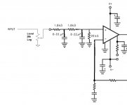
With your circuit as drawn, the 3dB cutoff of the filter will be ~145 Hz, not 400Hz. It will also have quite a bit of overshoot (ringing).
If it were me, I would use the circuit in the attached diagram. 400Hz Fc with a Bessel response (no overshoot, constant group delay). If you want an LR response, then make both caps 220n.
Attachments
Cascaded second order filters like this are common in tube amp and preamp power supplies. The filtering would be very inadequate if they were only first order.
The s domain transfer function is: (1/(1+sRC)) * (1/(1+sRC)), or 1/(1+2sRC+(sRC)^2). This is clearly second order (notice the s^2 term), with a 12dB/octave, or 40dB/decade, asymptote.
Hi,
Techobabble doesn't change the fact is clearly isn't second order,
in any rigourous sense, as its not a perfect cascade in any sense.
Very obvious looking at the circuit, what are you people missing ?
rgds, sreten.
Last edited:
I think you are ignoring the way the second CR loads the first CR, and the 20k loads the second CR. Your formula would be correct if there were buffers between them and after them.rayma said:The s domain transfer function is: (1/(1+sRC)) * (1/(1+sRC)), or 1/(1+2sRC+(sRC)^2).
My algebra (ignoring the 20k load) gives 1/(1 +3sCR + (sCR)^2). This is second order Gaussian?
I think you are ignoring the way the second CR loads the first CR, and the 20k loads the second CR. Your formula would be correct if there were buffers between them and after them.
My algebra (ignoring the 20k load) gives 1/(1 +3sCR + (sCR)^2). This is second order Gaussian?
Yes, that was for the RC - buffer - RC version, which gives a coefficient of 2 on the first order term, better than the 3 of the unbuffered version. An active second order filter will be better than either of these near the knee.
- Status
- This old topic is closed. If you want to reopen this topic, contact a moderator using the "Report Post" button.
- Home
- Source & Line
- Analog Line Level
- help with 2 pole low pass filter/attenuator