Hello everyone,
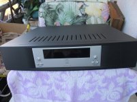
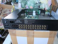
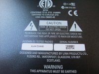
I'm trying to repair a Linn Exotik/S standard (non DA version) preamp. This preamp uses all surface mount PCB architecture including the switch mode power supply. The serial number is partially unreadable due to an abrasion that has occurred in the past. The last four digits are 0134 however. I don't know if a firmware upgrade (if even available) was ever performed.
When powered up from totally cold and being off for more than 2 hours, front panel controls & remote commands function normally & line draw is 15 watts. Then, after about 15 minutes, all functions freeze.
The display confirms the locked up condition & it makes no difference whether commands are issued from the remote or directly via the front panel, it remains locked up. Functioning can be restored to normal by turning off the rear panel line switch, then turning it back on. It is not necessary to leave this switch off for more than about 3 seconds to restore normal function. Signal throughput remains unaffected, but no control of volume or source switching is possible.
When left powered up fully (15 watt line draw), for an hour or more, the time to function lockup goes down considerably to about 90 seconds or less after cycling the rear panel line switch. Using a fan with the top cover off makes no difference to this problem.
I found two defective 100mFd 35v caps in the power supply (C201 & C214) & replaced them with Panasonic FC series caps of a higher voltage, however the problem remains. The power supply also sporadically turns off with no button pushes & goes into 7 watt line draw mode unpredictably & infrequently. It will come out of 7 watt mode & into 15 watt mode consistently with any front panel button push.
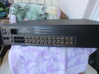
I measured the voltage at all 8 pins of the power supply output connector during both normal & abnormal functioning, but there is no difference in voltage. I also used a scope to look for noise on these pins & found the noise level to be less than about .05 volt. The measured power supply pin voltages were:
Brown +13.6V
Red 0
Orange -13.5V
Yellow +0.13
Green +6.44
Blue 0
Purple 0
Grey -6.81
I also checked for intermittent solder joints & connections, but no evidence was found
I can't find a service manual for this online. Can anyone suggest what might be causing this lock up, latch up, freeze, or whatever it might be called problem?
Thank you")
I'm trying to repair a Linn Exotik/S standard (non DA version) preamp. This preamp uses all surface mount PCB architecture including the switch mode power supply. The serial number is partially unreadable due to an abrasion that has occurred in the past. The last four digits are 0134 however. I don't know if a firmware upgrade (if even available) was ever performed.
When powered up from totally cold and being off for more than 2 hours, front panel controls & remote commands function normally & line draw is 15 watts. Then, after about 15 minutes, all functions freeze.
The display confirms the locked up condition & it makes no difference whether commands are issued from the remote or directly via the front panel, it remains locked up. Functioning can be restored to normal by turning off the rear panel line switch, then turning it back on. It is not necessary to leave this switch off for more than about 3 seconds to restore normal function. Signal throughput remains unaffected, but no control of volume or source switching is possible.
When left powered up fully (15 watt line draw), for an hour or more, the time to function lockup goes down considerably to about 90 seconds or less after cycling the rear panel line switch. Using a fan with the top cover off makes no difference to this problem.
I found two defective 100mFd 35v caps in the power supply (C201 & C214) & replaced them with Panasonic FC series caps of a higher voltage, however the problem remains. The power supply also sporadically turns off with no button pushes & goes into 7 watt line draw mode unpredictably & infrequently. It will come out of 7 watt mode & into 15 watt mode consistently with any front panel button push.
I measured the voltage at all 8 pins of the power supply output connector during both normal & abnormal functioning, but there is no difference in voltage. I also used a scope to look for noise on these pins & found the noise level to be less than about .05 volt. The measured power supply pin voltages were:
Brown +13.6V
Red 0
Orange -13.5V
Yellow +0.13
Green +6.44
Blue 0
Purple 0
Grey -6.81
I also checked for intermittent solder joints & connections, but no evidence was found
I can't find a service manual for this online. Can anyone suggest what might be causing this lock up, latch up, freeze, or whatever it might be called problem?
Thank you
Thank you gmphadte, but as stated in my opening post, I have already checked for bad solder joints. This was done by gently tapping on the PCBs both during the lock up phase and during normal operation.
As stated previously, I also used a cooling fan both during the lock up phase and during normal operation. No improvement or change was observed during either test.
I would think that if operation is restored to normal (for a time anyway) simply by turning the rear panel power switch Off and back On with as short as a 2 second Off period, that would eliminate thermal expansion effects on faulty solder joints from consideration, especially when tested with the above mentioned cooling fan.
Thank you Gajanan,
I have now carefully reflowed most of the ICs with a little flux, but no extra solder of course. I inspected all of their pins with a 30X eyeloupe and did find a few (U101, U102, U200, U201, & U202) to have partially suspect solder joints. U203 to U206 run the hottest and they were reflowed as well. Unfortunately no improvement was noted. I also reflowed a few joints in the power supply after inspecting with a 30X eyeloupe. No improvement.
An interesting thing was noted however. Despite this unit having a 100V to 240V auto ranging SMPS, the preamp will not turn on (with the normal accompanying click from SMPS relay L102) with a variac set to 145VAC. It will turn on at 140VAC and down to 100VAC however. I am now testing at 100VAC to see if the problem is helped by lower line voltage.
This SMPS auto ranges between 100V to 120V and 220V to 240V line voltage unless I'm missing something. That would make the above mentioned 145V non power up condition normal. I did check to see what line voltage the SMPS would turn off. It was 83V.
Further tests show that running at 100V or 120V line voltage makes no difference to the lock up problem.
Further tests show that running at 100V or 120V line voltage makes no difference to the lock up problem.
Normally open 12 volt relay RL101 (sorry not L102 as previously stated) on SMPS clicks on fine, there are no defective solder joints, and contacts have near zero resistance.
The problem is that although this relay does not click off when the problem manifests, it does receive a constant over voltage to the actuating coil of 13.27VDC. The rated operate voltage for this Tyco RE030012 relay is 8.4VDC. It seems to me that 13.27VDC is way too high of a hold voltage for a 12 volt relay. Sadly this does not seem to be the problem however.
I did find suspect solder joints at U13, U12, U6, and U15 of the front panel PCB and I did rectify those issues. It seemed that did the trick, as the unit did not lock up for a record setting time, but alas, it did eventually lock up. Very, very frustrating....
Technical Manual, Circuit Description and Schematic wanted
the main reason for the mentioned costs are the fact, that Linn only replace the whole PCB for the switch mode power supply.
Who can upload at least the schematic both for the switch mode power supply, main PCB and front PCB.
What are the necessary steps to remove the SMPS PCB for (de-)solder and replace the parts ?
Thank you for an advice.
Attachments
-
 DSCF7214.jpg982.9 KB · Views: 179
 -
 DSCF7224.jpg889.9 KB · Views: 142
 -
 DSCF7225.jpg850 KB · Views: 129
 -
 DSCF7230.jpg870.9 KB · Views: 134
 -
 DSCF7218.jpg993.5 KB · Views: 150
 -
 DSCF7212.jpg935.3 KB · Views: 224
 -
 DSCF7210.jpg885.3 KB · Views: 174
 -
 DSCF7200.jpg1,001.8 KB · Views: 158
 -
 DSCF7155.jpg1,000 KB · Views: 178
 -
 DSCF7150.jpg1,005.4 KB · Views: 175
the main reason for the mentioned costs are the fact, that Linn only replace the whole PCB for the switch mode power supply.
Who can upload at least the schematic both for the switch mode power supply, main PCB and front PCB.
What are the necessary steps to remove the SMPS PCB for (de-)solder and replace the parts ?
Thank you for an advice.
Last month I had a different unit with a diffrenet SMPS, LINN refused to send the service manual, they said that you have to buy a new one.
I tried to fix that, but I was not patient enough to do it, so I returned it to the customer.
IR2110 was damaged + 2 IGBTS+ the current sense resisitors
Its now going to the bin, sadly
If one have at least 4 or 5 devices of the same SMPS-model resp. version the creation of the circuit diagram with help of the PCB and the repair should be worthwhile.
This I have done on the brilliant SMPS - check out last PDF attachment in post #5 under
Linn "LINTO" MC Preamp Schematic without SMPS - Schematic for SMPS wanted
With help of this so as the datasheets of the used ICs a refurbishing is mostly an easy task (approximately 20 devices of this version work fine again after replace the caps).
In the majority of all cases, poor quality electrolytic capacitors with a low voltage (6V/10V/16V/25V) are the reason - at best still replacing at least by 63V version (63VDC provide lowest ESR value).
Maybe another guy have already perform a schematic on the SMPS of your version.
Last edited:
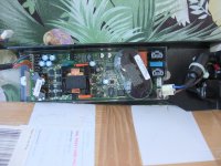
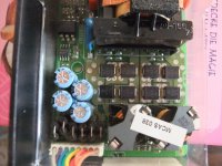
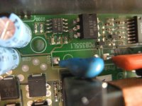
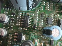
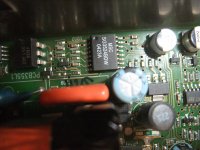
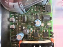
According this PCB there are no special parts in use except the transformer:
SG3524BDW PWM controller (very very old)
https://www.ti.com/lit/ds/symlink/u...l=https%3A%2F%2Fwww.ti.com%2Fproduct%2FUC2524
XR-2524 datasheet
VB408B High Voltage Regulator
VB408 datasheet
IR2110 H-Bridge
https://cdn-reichelt.de/documents/datenblatt/A200/IR2110_IR2110S_IR2113_IR2113S.pdf
IR2110 pdf, IR2110 description, IR2110 datasheets, IR2110 view ::: ALLDATASHEET :::
With help of this datasheets creating schematic must actually be an easy task. A bit effort need the de-solder and measuring the chip caps without code resp. printed value.
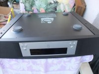
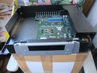
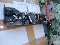
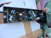
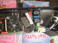
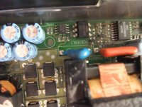
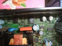
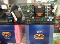
For me the most interesting question is in the moment, what are the necessary steps to remove the SMPS PCB for (de-)solder and replace the parts (go to the first both images) ? I can't discover screws therefore.
Thank you for an advice.
SG3524BDW PWM controller (very very old)
https://www.ti.com/lit/ds/symlink/u...l=https%3A%2F%2Fwww.ti.com%2Fproduct%2FUC2524
XR-2524 datasheet
VB408B High Voltage Regulator
VB408 datasheet
IR2110 H-Bridge
https://cdn-reichelt.de/documents/datenblatt/A200/IR2110_IR2110S_IR2113_IR2113S.pdf
IR2110 pdf, IR2110 description, IR2110 datasheets, IR2110 view ::: ALLDATASHEET :::
With help of this datasheets creating schematic must actually be an easy task. A bit effort need the de-solder and measuring the chip caps without code resp. printed value.
For me the most interesting question is in the moment, what are the necessary steps to remove the SMPS PCB for (de-)solder and replace the parts (go to the first both images) ? I can't discover screws therefore.
Thank you for an advice.
Attachments
-
 Linn PCB355L1 - SMPS-1.jpg984.8 KB · Views: 84
 -
 Linn PCB355L1 - SMPS-2.jpg942.2 KB · Views: 85
 -
 Linn PCB355L1 - SMPS-3.jpg1,000.5 KB · Views: 107
 -
 Linn PCB355L1 - SMPS-4.jpg1,012 KB · Views: 87
 -
 Linn PCB355L1 - SMPS-5.jpg1,004.8 KB · Views: 74
 -
 Linn PCB355L1 - SMPS-6.jpg1 MB · Views: 83
 -
 Linn PCB355L1 - SMPS-7.jpg999 KB · Views: 78
 -
 Linn PCB355L1 - SMPS-8.jpg1,005.7 KB · Views: 81
 -
 Linn PCB355L1 - SMPS-9.jpg1,012.2 KB · Views: 77
 -
 Linn PCB355L1 - SMPS-10.jpg1,021.9 KB · Views: 86
Last edited:
i am not a qualified tech however I found replacing all the electrolytic caps in the smps with newer good quality replacements designed for smps use and replacing the electro's on the main board can help with quite a number of issues seen on Linn products. Linn run a lot of their products on the hot side and many of the caps are only rated for 85`C. I always use 105`C as replacements when possible.
without schematic this is the only step to perform. But for troubleshooting in detail schematic is necessary.
Troubleshooting switch mode power supplies
Troubleshooting switch mode power supplies
Hi there, just found this thread. I have the same issue with 2 units, one DA (essentially a Accurate Pre) and one non-DA. The issue already occurred about 5 years ago and was repaired in a Linn shop. No description was give what was done, but I found 2 caps in a bag. Upon close inspection of the boards, I found the replaced caps on the front panel board.
Exchanging the front panel boards with the (then working) non-DA I concluded that the issue is caused by the front panel board, not PSU or main/DA board. I intend to replace the caps on both boards and see if this solves the issue for another 5 years.
Exchanging the front panel boards with the (then working) non-DA I concluded that the issue is caused by the front panel board, not PSU or main/DA board. I intend to replace the caps on both boards and see if this solves the issue for another 5 years.
any news concerning schematic ?without schematic this is the only step to perform. But for troubleshooting in detail schematic is necessary.
Troubleshooting switch mode power supplies
For replace several jFET's for mute control I start this thread:
https://www.diyaudio.com/forums/ana...witch-function-pre-amplifier.html#post6871935
- Home
- Source & Line
- Analog Line Level
- Linn Exotik/S non DA version lock up problem