when you know why a ground plane works and how to design it so that it can achieve those desirable attributes, then add in planes for -ve power and +ve power and signal ground and power ground.
That is a minimum of 4 extra planes.
If you don't know why planes work, or you don't know how to make them work for your circuit, then forget ground planes.
Just make sure all your connections are close coupled two wire (or two trace) Flow and Return from Source and back.
That is a minimum of 4 extra planes.
If you don't know why planes work, or you don't know how to make them work for your circuit, then forget ground planes.
Just make sure all your connections are close coupled two wire (or two trace) Flow and Return from Source and back.
when you know why a ground plane works and how to design it so that it can achieve those desirable attributes, then add in planes for -ve power and +ve power and signal ground and power ground.
That is a minimum of 4 extra planes.
Andrew, I'm interested to know why other planes are necessary?
 I understand a ground plane is important to stop any instability in such a low-level circuit as a phono stage (and you can separate signal ground from power ground with a 10ohm res) ... but I can't see why -ve power and +ve power grounds are required?
Thanks,
Andy
The following from TI has some good info on ground planes and power planes and why you would want to use them http://www.ti.com/lit/ml/sloa089/sloa089.pdf
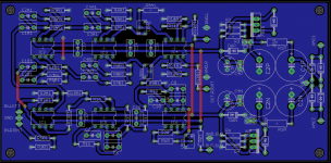
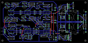
I decided to go with a ground plane to simplify grounding after reading the linked TI document. Whether it was the right decsion or not I guess I won't know unless I try a more traditional board layout.
Tony.
I decided to go with a ground plane to simplify grounding after reading the linked TI document. Whether it was the right decsion or not I guess I won't know unless I try a more traditional board layout.
Tony.
The flow current has to have the ability to RETURN in a plane that is VERY CLOSE to the flow layer.
This applies to all current flows, not just the music signal.
It applies to the +ve supply current flow and the -ve supply current flow and the signal current flow.
To achieve the "VERY CLOSE", each flow layer NEEDS it's return layer adjacent to it and preferably <10thou (10mil, 0.25mm) of dielectric between the adjacent layers. H.OTT describes why 4 layer and 5layer pCBs don't get the full potential from planes. He goes on to describe why 8layer to 12layer PCBs can be made to work well.
It's knowing WHY the multi-layers work, that enables one to learn HOW to assemble the PCB layers to allow them to give the advantages.
60thou (60mil, 1.5mm) of layer separation of a standard 2layer PCB does not get close.
Last edited:
As an example, a ground plane underneath the inverting input of an op amp will add shunt capacitance to ground and de-stabilize it slightly; they don't automatically make things more stable.
Not that they shouldn't be used, but as with anything, the details are important. I personally like to think of a ground plane as a really wide trace, and the good part of that is that a wide trace has less inductance for a given length. A ground plane also can let you turn a trace into a transmission line if you're doing RF, it can act as a Faraday shield between layers, and you can get shunt capacitance out of it too.
Not that they shouldn't be used, but as with anything, the details are important. I personally like to think of a ground plane as a really wide trace, and the good part of that is that a wide trace has less inductance for a given length. A ground plane also can let you turn a trace into a transmission line if you're doing RF, it can act as a Faraday shield between layers, and you can get shunt capacitance out of it too.
- Status
- This old topic is closed. If you want to reopen this topic, contact a moderator using the "Report Post" button.
- Home
- Source & Line
- Analog Line Level
- question on crossover board layout