Hello,
I was just wondering if anybody here has experience with these pots?
I am looking to to the quad ganged POT from the PTD904 series to do volume control on dual (stereo) differential lines.
Any other good options available for quad ganged pots? Since these will be on the input to a diff amp I am worried about common mode rejection. because if they are not too well matched it will cause problems.
http://www.bourns.com/data/global/pdfs/PTD90.pdf
Also what about Vishay P11A series:
http://www.vishay.com/docs/51031/p11.pdf
Thanks for any help.
Last edited:
If there is one thing I would not bet my life on, it's super-accurate pot tracking. You'll be lucky to get a 0.1 dB match with a bit of a following wind, certainly far worse near the low end.Since these will be on the input to a diff amp I am worried about common mode rejection. because if they are not too well matched it will cause problems.
I realized that I cannot use the pot's in the way that I was planning so, i am readjusting the circuit to attenuate at the output of the op-amp instead of at the input that.
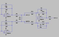
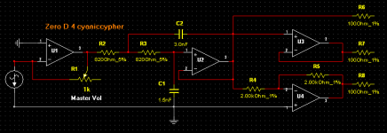
Here is the circuit I am providing a differential and a single ended output. The input impedance of the devices that this is going to is pretty high so the input impedance in the 300 ohm range will not hurt.
In the image R7 is a 10k pot.
I found a place to buy dual 10k Alps Blue Velvet pots
Here is the circuit I am providing a differential and a single ended output. The input impedance of the devices that this is going to is pretty high so the input impedance in the 300 ohm range will not hurt.
In the image R7 is a 10k pot.
I found a place to buy dual 10k Alps Blue Velvet pots
Attachments
Hi, your screenie is missing the previous part. If you post it complete i might have another solution for you")
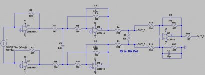
Here you go.
Attachments
I am looking to to the quad ganged pot .. to do volume control on dual (stereo) differential lines.
In your last screenie you show an Unbalanced output feeding the circuit. So have you considered putting the 4 gang pot in that position ?
You seem to have made it more complicated than necessesary. You have the unbalanced out "appearing" to be converted to balanced, Twice ? Then converted back to unbalanced.
I say "appearing" because U1 - U4 are ALL in inverting mode ? Which means you would Nothing out of U3 & U4 as they would cancel out !
So you could eliminate U3 & U4 for starters.
Let me know what you think, & we'll take it from there.
Attachments
Looks like an I/V stage for a DAC, huh?
Believe it or not, the usual way of handling this is going to single-ended, doing voluming control + gain and then converting back to balanced where needed.
See attached. Let me know what you think please. R18 is the pot.
Attachments
In your last screenie you show an Unbalanced output feeding the circuit. So have you considered putting the 4 gang pot in that position ?
You seem to have made it more complicated than necessesary. You have the unbalanced out "appearing" to be converted to balanced, Twice ? Then converted back to unbalanced.
I say "appearing" because U1 - U4 are ALL in inverting mode ? Which means you would Nothing out of U3 & U4 as they would cancel out !
So you could eliminate U3 & U4 for starters.
Let me know what you think, & we'll take it from there.
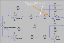
The input current source is differential.
Also the feedback is the way it is because it is a mulitple-feedback low pass filter topology, I have found that it works better then what you are suggesting.
@ cyaniccypher
I don't use LTS, & i didn't recognise the input signal labeling as an differential input current source at first ! The LPF looks more like a sallen/key type circuit than a mulitple-feedback one. Why is the f3 so high ?
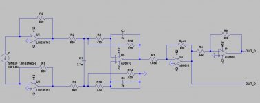
Anyway, have a look at the circuit i've designed & see what you think. It's a Lot simpler & appears to do what you want. I've only used one output from the current source, but it still works. You could replace R1 with a larger value to get more gain, if required.
I don't use LTS, & i didn't recognise the input signal labeling as an differential input current source at first ! The LPF looks more like a sallen/key type circuit than a mulitple-feedback one. Why is the f3 so high ?
Anyway, have a look at the circuit i've designed & see what you think. It's a Lot simpler & appears to do what you want. I've only used one output from the current source, but it still works. You could replace R1 with a larger value to get more gain, if required.
Attachments
@ cyaniccypher
I don't use LTS, & i didn't recognise the input signal labeling as an differential input current source at first ! The LPF looks more like a sallen/key type circuit than a mulitple-feedback one. Why is the f3 so high ?
Anyway, have a look at the circuit i've designed & see what you think. It's a Lot simpler & appears to do what you want. I've only used one output from the current source, but it still works. You could replace R1 with a larger value to get more gain, if required.
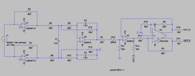
Thank you for that. I do not have a choice with the current output because I am using a PCM1794A which has a differential output. Or rather two single ended outputs that are 180 out of phase.
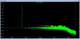
I am using your circuit for differential output though it is working really well in the simulation in real word I will never see a noise floor of -210dB.
R7 will be 2k and Rpot will be a 1k pot in the final design.
Attachments
Thank you for that.
Pleasure
I do not have a choice with the current output because I am using a PCM1794A which has a differential output. Or rather two single ended outputs that are 180 out of phase.
Yes you do have a choice, as i mentioned & showed in my previous post & screenie. By taking just the + or - output from the PCM1794A & feeding into my circuit, will still produce a complete sinewave signal @ U1's output pin.
I am using your circuit for differential output though it is working really well in the simulation in real word I will never see a noise floor of -210dB.
Well it's similar to my circuit, & will work, but you are creating a unnecessary propagation delay @ U4's output. That's because you've taken U4's input from U3's output. If you notice how i did it, there is no extra PD because the inputs to U3 & U4 are both connected directly to U2's output.
R7 will be 2k and Rpot will be a 1k pot in the final design.
It should be the other way round, otherwise you will get a variation of -6dB to zero.
Also your curcuit uses 5 OPA's, where mine only needs 4.
Where is the unbalanced output in your circuit ?
I'm still not convinced about your LPF circuit though. And Why is the f3 set so high for it ?
Also doesn't pot in the feedback loop normally need a reverse log lot (hens teeth are easier to obtain)?
Also, doing it that way, when that pot gets even slightly intermittent on the wiper contact, you are asking for nasty noises.
Why not just do the standard thing, pot from U5 to ground (With a DC block cap) U3,4 are a simple buffer, easy, obvious and no opamps running at less then unity gain, so should be stable.
Regards, Dan.
Hi Dan
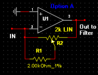
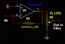
To take any concern away from that, cyaniccypher could use the trick of faking a Log pot as shown in Option A. If he wants more gain he just needs to scale up R1 & R2. Also by using my total circuit he Only needs a dual pot instead of a quad.
Good point, though i've never had issues. The unconnected end of the pot could be connected to the slider which would eliminate any concern about that. My Option A also covers that too.
He could, if he went with the more complicated 5 OPA circuit, but would require a quad pot ! With my 4 OPA circuit he could do Option B, still with a dual pot.
Fitting some DC isolating caps on the outputs wouldn't hurt, eg 10uf - 100uf.
Regards to both
Originally Posted by dmills
Also doesn't pot in the feedback loop normally need a reverse log lot (hens teeth are easier to obtain)?
To take any concern away from that, cyaniccypher could use the trick of faking a Log pot as shown in Option A. If he wants more gain he just needs to scale up R1 & R2. Also by using my total circuit he Only needs a dual pot instead of a quad.
Also, doing it that way, when that pot gets even slightly intermittent on the wiper contact, you are asking for nasty noises.
Good point, though i've never had issues. The unconnected end of the pot could be connected to the slider which would eliminate any concern about that. My Option A also covers that too.
Why not just do the standard thing, pot from U5 to ground (With a DC block cap) U3,4 are a simple buffer, easy, obvious and no opamps running at less then unity gain, so should be stable.
He could, if he went with the more complicated 5 OPA circuit, but would require a quad pot ! With my 4 OPA circuit he could do Option B, still with a dual pot.
Fitting some DC isolating caps on the outputs wouldn't hurt, eg 10uf - 100uf.
Regards to both
Attachments

@ cyaniccypher
1 - Why have you chosen the frequency of the filter to be as high as it is ?
With the filter the way it is there is already -.4dB attentuation at 20kHz. If I move the filter in any more it will start cutting into audio range and I do not want this.
Pot will be 100k.2 - What will the value of the pot be ?
Originally Posted by cyaniccypher
I will use the circuit below,
So you don't want to use the 4 OPA circuit with other fewer components too, & still acheive what you want. OK by me
you are correct with the propagation delay from the circuit i had before.
I am putting another resistor in series with the pot because when the pot is at 0 ohm i do not want the gain to be too high.
I see.
With the filter the way it is there is already -.4dB attentuation at 20kHz. If I move the filter in any more it will start cutting into audio range and I do not want this
OK.
Pot will be 100k.
It'll give you a lot of attenuation, but might be noisy !
- Status
- This old topic is closed. If you want to reopen this topic, contact a moderator using the "Report Post" button.
- Home
- Source & Line
- Analog Line Level
- Bourns PTD90 Series Potentiometer