Hey guys i am a Auto Electrician and electronics is my pass time.
I am making a low pass filter based on the tL074 for my Amplifier i just installed. Here is a link to the Install. The amp has no setting for LP
forums.justcommodores.com.au/ve-holden-commodore-2006-2013/232418-amplifier-install-nxt-battery.html
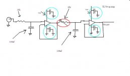
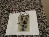
Here is very rough drawing i did of the circuit it is very basic 1st order cascaded. Surprisingly it works pretty good.
The input is on the non inverting pin
I am trying to change the frequency via a variable resistor. Circled red on the diagram but does nothing is there a reason why? Changing the Cap has more effect on the frequency then changing resistor
Also circled in blue Are capacitors i put 100nf ceramic type caps is this correct.
Thank you
I am making a low pass filter based on the tL074 for my Amplifier i just installed. Here is a link to the Install. The amp has no setting for LP
forums.justcommodores.com.au/ve-holden-commodore-2006-2013/232418-amplifier-install-nxt-battery.html
Here is very rough drawing i did of the circuit it is very basic 1st order cascaded. Surprisingly it works pretty good.
The input is on the non inverting pin
I am trying to change the frequency via a variable resistor. Circled red on the diagram but does nothing is there a reason why? Changing the Cap has more effect on the frequency then changing resistor
Also circled in blue Are capacitors i put 100nf ceramic type caps is this correct.
Thank you
Attachments
Hi, i'm presuming the reason it does nothing, is that you havn't connected the wiper ?
Yes the 100nf are fine.
Hey mate thanks for the reply.
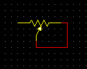
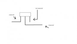
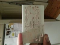
I have connected the variable resistor so that the resistance fluctuates when you turn the wiper. leaving one terminal not in use here a pic.
Also i am not using a virtual ground i am using the earth from the rca if this helps.
Attachments
Yeah that pot wiring would work too. If ALL the connections & soldered joints are 100% ok, i'm surprised you don't hear ANY change. You might like to try a different pot of say 47k as that should help.
Also you MUST put a resistor of @ least 1k in series with the pot, because the OpAmp won't like a capacitor between it's output & ground if the pot is at zero resistance !
*******
Ahh, i missed the fact that you're using the OpAmp off a single supply. Well you can't use that circuit like that then !
I'll post back this evening with a better circuit for you. I'm going out for sunday lunch etc very shortly")
Also you MUST put a resistor of @ least 1k in series with the pot, because the OpAmp won't like a capacitor between it's output & ground if the pot is at zero resistance !
*******
Ahh, i missed the fact that you're using the OpAmp off a single supply. Well you can't use that circuit like that then !
I'll post back this evening with a better circuit for you. I'm going out for sunday lunch etc very shortly
Yeah that pot wiring would work too. If ALL the connections & soldered joints are 100% ok, i'm surprised you don't hear ANY change. You might like to try a different pot of say 47k as that should help.
Also you MUST put a resistor of @ least 1k in series with the pot, because the OpAmp won't like a capacitor between it's output & ground if the pot is at zero resistance !
*******
Ahh, i missed the fact that you're using the OpAmp off a single supply. Well you can't use that circuit like that then !
I'll post back this evening with a better circuit for you. I'm going out for sunday lunch etc very shortly
Hey mate thanks for your reply and help
Can you pls explain why I would not be able to use this circuit because it seems to work. I just want to know for future reference.
I tried sallen key topology but seems to have high distortion with the feedback cap.
Thanks.
As promised i'm back, later than advertised, but it turned into more than afternoon
I'm wondering why you're using a quad OpAmp. Is it because you're making a stereo filter, & only showed one channel, & will actually be duplicating the circuit ? If so then use a stereo ganged pot. If not use a TL072, but the pin numbers will be different of course !
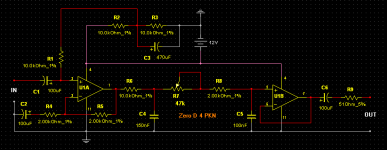
Anyway, the fact that you're on a single 12V power supply, means that you have to power it differently, as you do need a Virtual earth. See my circuit below.
Your circuit might be working in some kind of fashion, but not correctly. Most OpAmps are designed to run off dual + & - power supplys, as are the TL074/72. If you want to use a single supply you have to fake it, by arranging for a half way point, = Virtual Earth/Ground. In this case 6 Volts. This is made with R2 & R3 & C3.
Plus you need electrolytic capacitors to block the DC getting out to the previous & later equipment. That's what C1 & C6 are for.
I've also given the circuit X 2 gain, = R4 & R5 which should help.
I've simmed the circuit & it appears to work fine & do what you require
I'm wondering why you're using a quad OpAmp. Is it because you're making a stereo filter, & only showed one channel, & will actually be duplicating the circuit ? If so then use a stereo ganged pot. If not use a TL072, but the pin numbers will be different of course !
Anyway, the fact that you're on a single 12V power supply, means that you have to power it differently, as you do need a Virtual earth. See my circuit below.
Your circuit might be working in some kind of fashion, but not correctly. Most OpAmps are designed to run off dual + & - power supplys, as are the TL074/72. If you want to use a single supply you have to fake it, by arranging for a half way point, = Virtual Earth/Ground. In this case 6 Volts. This is made with R2 & R3 & C3.
Plus you need electrolytic capacitors to block the DC getting out to the previous & later equipment. That's what C1 & C6 are for.
I've also given the circuit X 2 gain, = R4 & R5 which should help.
I've simmed the circuit & it appears to work fine & do what you require
Attachments
As promised i'm back, later than advertised, but it turned into more than afternoon
I'm wondering why you're using a quad OpAmp. Is it because you're making a stereo filter, & only showed one channel, & will actually be duplicating the circuit ? If so then use a stereo ganged pot. If not use a TL072, but the pin numbers will be different of course !
Anyway, the fact that you're on a single 12V power supply, means that you have to power it differently, as you do need a Virtual earth. See my circuit below.
Your circuit might be working in some kind of fashion, but not correctly. Most OpAmps are designed to run off dual + & - power supplys, as are the TL074/72. If you want to use a single supply you have to fake it, by arranging for a half way point, = Virtual Earth/Ground. In this case 6 Volts. This is made with R2 & R3 & C3.
Plus you need electrolytic capacitors to block the DC getting out to the previous & later equipment. That's what C1 & C6 are for.
I've also given the circuit X 2 gain, = R4 & R5 which should help.
I've simmed the circuit & it appears to work fine & do what you require
Hey mate thanks for your reply and help
You are correct in saying that i will be duplicating this circuit for left and right channel to the amplifier.
I will study this circuit and make it on my bread board and report back.
Thank you.
I think your cascaded RC filters result in an LR2 characteristic.
To maintain that, you must change both resistor values by the same amount.
To help with keeping the resistor change equal you can add a series resistor to each variable resistor. Try 4k7 as a starter.
It will allow you to change the roll off frequency of the LR2 from 50Hz (when VR is maximum) to 156Hz (when VR is minimum).
A 10k linear dual track is generally better matched than a log dual pot.
If you want a smaller range of adjustment then use a higher value than 4k7 for the series resistors.
@ PKN
If you want to use a variable resistor/POT in both positions, you can. But as you showed only one in your initial sketch, i thought that's what you wanted !
Either way will work though.
Thanks mate you guys have been really helpfull. Sorry about the miss understanding.
I will try your circuit you designed for me and report back today.
Your design looks good and I will learn how to implement this in future projects.
Thank you
R5 & R4 set the gain of the first stage.
The gain for a non-inverting topology is 1+[R5/R4]
Change either R4 or R5 to change the gain, i.e. change the ratio of R4:R5.
You MUST use a unity gain stable opamp.
Thanks for your reply mate.
I will do some test on this part of the circuit tomorrow and see what happens.
Thank you
Originally Posted by PKN
Your design looks good and I will learn how to implement this in future projects
I have made the circuit you provided for me. It works
Nice to hear
If i was to put a variable resistor on R5 say 5k or 10k this should increase the gain?
Yes it will, but due to the limited amount of headroom you have running on 12V, you could easily clip/distort the signal. I doubt whether you will need much gain though.
R5 is the best position to replace the resistor. I would expect a 5k to give you more than enough gain, but if even you choose a 10K obviously you can still set it lower.
Hi, looking good !
Did you build it Exactly as in my Post #6 ? Also as i don't see variable resistors on the R5's, what value are the fixed resistors ?
Hey mate thanks. Yeh i used your circuit design. Did a test run today it works good.
I did not use the gain option I am running it on unity gain. It sounded fine with no gain. If i need more i will use the amplifier gain to boost it a bit.
Thanks for all your help. I will post pics of the housing once i made it.
Thanks
- Status
- This old topic is closed. If you want to reopen this topic, contact a moderator using the "Report Post" button.
- Home
- Source & Line
- Analog Line Level
- Active Low Pass