Hello, I have a vintage HH Electronics X300 2/3 way active crossover which I am using in 3 way mode (with 3 HH VX series MOS-FET power amps) and I wonder if anyone can help me with a couple of points to do with its extremes of frequency response? Firstly, since it is intended as a professional device, it has a 35Hz high pass filter for driver protection. The FR graph I have shows this as starting at about 50Hz and rolling off at 18dB/octave (Butterworth filter I believe). I would like to remove this "sub-bass" filter from the crossover since my speakers will respond flat at least an octave below this point and it seems a shame to lose the bass. I have the schematic for this device (although I'm not sure how to upload it to this forum) but I need some guidance in what needs removing and what needs reconnecting to remove this function. Can anyone help?
I am also wondering about the upper frequency extreme, my power amps and speakers are fairly flat to well over 30KHz but this X300 FR starts to roll off at about 15KHz and is a few dB down by 20 KHz. The circuit is designed around TL071 op amps doing all the I/O buffering and 4739 op amps in the filter circuits. Are these limiting the FR? Also, are there any modern pin-for-pin replacements that would improve this crossover?
I look forward to any assistance you might be able to give
My only suggestion is ... go to Rod Elliott's web-site, get yourself a pair of his P09 PCBs ... + the P05 board, if you need a basic PS to power them.
Rod's site is here: ESP Projects Pages - DIY Audio and Electronics
Alternatively, if your speakers happen to have a bass LP / mid HP point at 330Hz and a mid LP / tweeter HP point at 2,600Hz, and your drivers can take 18DB bass LP with 12dB elsewhere, you might like to buy my current made-up P09 boards. (I will be removing them soon and going to a different XO regime.)
Regards,
Andy
Thanks for the idea, and it is a valid one, but what I really want to do is to modify the x-over I already have.
My only suggestion is ... go to Rod Elliott's web-site, get yourself a pair of his P09 PCBs ... + the P05 board, if you need a basic PS to power them.
Rod's site is here: ESP Projects Pages - DIY Audio and Electronics
Alternatively, if your speakers happen to have a bass LP / mid HP point at 330Hz and a mid LP / tweeter HP point at 2,600Hz, and your drivers can take 18DB bass LP with 12dB elsewhere, you might like to buy my current made-up P09 boards. (I will be removing them soon and going to a different XO regime.)
Regards,
Andy
If you can't find a service manual/schematic, take a look here: Active Filters to help you recognize the appropriate filter section. I suspect in the 35 Hz high pass section you'll find at least one largish (1 µf or so) value cap in series with the signal followed by a fairly high value resistor to ground. Check the circuit aroound the op amp that follows using Linkwitz' formulae to identify the section. Then you have two options:
Bypass the 35 Hz high pass filter by cutting appropriate traces and jumpering.
or
Turn the filter into a buffer by removing appropriate parts and jumpering as needed.
Bypass the 35 Hz high pass filter by cutting appropriate traces and jumpering.
or
Turn the filter into a buffer by removing appropriate parts and jumpering as needed.
Thanks Bob, as I wrote in my original post I do have a schematic but thanks a lot I will look at the site you mention, I might be able to work it out from there. I could post the schematic here if I knew how to - using the Insert Image seems to just point to a URL but the schematic is on my computer....
If you can't find a service manual/schematic, take a look here: Active Filters to help you recognize the appropriate filter section. I suspect in the 35 Hz high pass section you'll find at least one largish (1 µf or so) value cap in series with the signal followed by a fairly high value resistor to ground. Check the circuit aroound the op amp that follows using Linkwitz' formulae to identify the section. Then you have two options:
Bypass the 35 Hz high pass filter by cutting appropriate traces and jumpering.
or
Turn the filter into a buffer by removing appropriate parts and jumpering as needed.
Aha, I had missed the Attach icon. Here is the detail from the schematic. I have the whole drawing but it is a large file and possibly irrelevant to my question. Coffee hhhhmmmm must make some!
Ahh missed that you had the schematic. It's early here and I hadn't had enough coffee.
Attach the schematic file to a post rather than try to insert a picture.

Aha, I had missed the Attach icon. Here is the detail from the schematic. I have the whole drawing but it is a large file and possibly irrelevant to my question. Coffee hhhhmmmm must make some!
Multiple feedback topology. Use TI Filter Pro to calculate response. Active Filter Design Application - FILTERPRO - TI Software Folder
Looks like the first RC is an RF filter, but use Linkwitz to calculate the corner frequency.
Do you have the part around IC5? That 6µF8 in series with the low pass looks suspiciously like a low frequency high pass filter...
Looks like the first RC is an RF filter, but use Linkwitz to calculate the corner frequency.
Do you have the part around IC5? That 6µF8 in series with the low pass looks suspiciously like a low frequency high pass filter...
Last edited:
The spec says it is a 35Hz sub-bass filter and I modelled it a Spice download which showed it starting to roll off at 50Hz and about 3dB down at 35 Hz so I think that is correct. I am getting an error message about the whole schematic (something to do with a missing security token) but I think that IC5 is part of the frequency division. I'll see if I can cut that section out of the drawing and post in a few minutes. Thanks for the help!
Multiple feedback topology. Use TI Filter Pro to calculate response. Active Filter Design Application - FILTERPRO - TI Software Folder
Looks like the first RC is an RF filter, but use Linkwitz to calculate the corner frequency.
Do you have the part around IC5? That 6µF8 in series with the low pass looks suspiciously like a low frequency high pass filter...
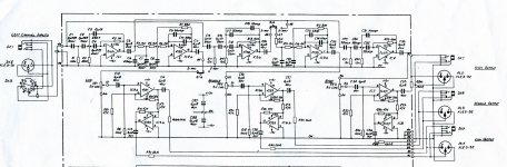
X300 Single channel
Here is the part of the schematic showing the left channel complete. I am wondering if more modern parts would improve the device, it rolls off at 20KHz but I would prefer it to go up to 30KHz+ - my tweeters do.
Here is the part of the schematic showing the left channel complete. I am wondering if more modern parts would improve the device, it rolls off at 20KHz but I would prefer it to go up to 30KHz+ - my tweeters do.
The spec says it is a 35Hz sub-bass filter and I modelled it a Spice download which showed it starting to roll off at 50Hz and about 3dB down at 35 Hz so I think that is correct. I am getting an error message about the whole schematic (something to do with a missing security token) but I think that IC5 is part of the frequency division. I'll see if I can cut that section out of the drawing and post in a few minutes. Thanks for the help!
Attachments
Thanks for the idea, and it is a valid one, but what I really want to do is to modify the x-over I already have.
Good luck!
") The concept of sow's ear into silk purse comes to mind!
The concept of sow's ear into silk purse comes to mind! And BTW, you said "it rolls off at 20KHz but I would prefer it to go up to 30KHz+" ... you need it to go up waaay past that, for the reduction at 20KHz not to be audible. We are not talking about "brick-wall" filters here so the XO needs to have a -3dB point (ie. the "roll-off") of a decade beyond 20KHz (which is 200KHz) for it not to be audible.
Do yourself a favour and have a look at Rod Elliott's P09 circuit diagram - the one you posted is too complicated ... simplicity is always better, grasshopper.
Andy
Last edited:
You might be right but HH was the Bryston of its time and used extensively by BBC other broadcasters, and in studios everywhere. I assume they knew what they were doing.
Good luck!
And BTW, you said "it rolls off at 20KHz but I would prefer it to go up to 30KHz+" ... you need it to go up waaay past that, for the reduction at 20KHz not to be audible. We are not talking about "brick-wall" filters here so the XO needs to have a -3dB point (ie. the "roll-off") of a decade beyond 20KHz (which is 200KHz) for it not to be audible.
Andy
You might be right but HH was the Bryston of its time and used extensively by BBC other broadcasters, and in studios everywhere. I assume they knew what they were doing.
"Of its time" is the key message there, mate.
And Bryston is by no means the "ne plus ultra" IMO - Pass, Accuphase, maybe.
Regards,
Andy
Plug the values around IC1 into Filter Pro, starting with C2. C1 and R1 form a first order 75 Hz high pass filter, if my calculations are correct. I'm going to venture a guess that IC1 is also a second order 75 Hz high pass. Ouch.
Edit: Read Linkwitz on designing active crossovers. We've come a long way since these filters if you are looking for high fidelity rather than PA use. Design the crossover to meet your drivers' filter requirements so that you get the acoustic slopes that you want. Symmetric slopes aren't always where you end up, although most commercial active crossovers force that. Phase alignment is important. My disinterested son noticed the difference without being asked when I got it right. It was nice to have independent confirmation of what I thought I was hearing.
Edit: Read Linkwitz on designing active crossovers. We've come a long way since these filters if you are looking for high fidelity rather than PA use. Design the crossover to meet your drivers' filter requirements so that you get the acoustic slopes that you want. Symmetric slopes aren't always where you end up, although most commercial active crossovers force that. Phase alignment is important. My disinterested son noticed the difference without being asked when I got it right. It was nice to have independent confirmation of what I thought I was hearing.
Last edited:
I'm having a lot of trouble downloading filter pro from the TI website, I don't know why. I will read the Linkwitz stuff and I'm sure things are better now but I still would like to see what this device can do.
I suppose hifi use is closest to what I want, it's a studio style system really though.
I suppose hifi use is closest to what I want, it's a studio style system really though.
Plug the values around IC1 into Filter Pro, starting with C2. C1 and R1 form a first order 75 Hz high pass filter, if my calculations are correct. I'm going to venture a guess that IC1 is also a second order 75 Hz high pass. Ouch.
Edit: Read Linkwitz on designing active crossovers. We've come a long way since these filters if you are looking for high fidelity rather than PA use. Design the crossover to meet your drivers' filter requirements so that you get the acoustic slopes that you want. Symmetric slopes aren't always where you end up, although most commercial active crossovers force that. Phase alignment is important. My disinterested son noticed the difference without being asked when I got it right. It was nice to have independent confirmation of what I thought I was hearing.
Definitely.
Are there large inaccuracies in this design? The spec says +/-2dB 40Hz-20KHz, THD <0.05% at 775mV 20Hz-20kHz, S/N 85dB unweighted. It doesn't look too bad to me. I got a copy of Filter Pro but I couldn't see how to enter the actual circuit values into it.
I may well not end up using this forever but I do want to get rid of the sub-bass filter.
I'd think a studio monitor you would want to be as accurate as possible.
An answer...
I have been told this:
You can keep the same filter characteristics but shift the whole thing lower if you want by keeping the component ratios the same. So if the 22n’s become 100n and the 10 becomes 47n (close enough) then the whole plot moves lower by 100/22 = 4.5. The 3db point will now be 35/4.5 = just under 8Hz. Now the phase shift happens at the same ratio lower of course. Obviously could use any ratio you want.
So I think I will give it a try.
- Status
- This old topic is closed. If you want to reopen this topic, contact a moderator using the "Report Post" button.
- Home
- Source & Line
- Analog Line Level
- Active Crossover frequency response - help needed HH X300