Yes their "manual" is not very clear at all !
The inverter IS shown as external to the Amp ! However, i "think" they are "attempting" to explain/show that, CH1 is inverted internally when the BTL sync pin is tied to ground.
Keep me posted,
Regards
No. BTL sync keeps the carrier frequencies (which are load-dependent on an ICEpower amp) aligned between the two amp channels but does not invert anything.
If you are feeding the amp from a balanced source the the inverter is not needed (because there is already an opposite phase signal applied). if you are feeding the amp from an SE source, then you'd need a way to generate a negative phase signal (ie. an inverter).
The ASX-modules are really two SE amps on the same board, so bridging it is not that different from bridging two LM3886-amps
")
/U.
@ Nisbeth
Thanks for the info about the sync, & confirming that the Amp does indeed require an external inverter, unless fed balanced. That's how it looked to me from their PDF.
From what i could gather, DQ828 isn't using a balanced feed, in which case he will need an external inverter.
@ DQ828
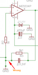
Your screenie in Post #20 is incorrect, see my Post #7 As you DO need an inverter, then it would be better to use a dual NE5534 = NE5532.
Thanks for the info about the sync, & confirming that the Amp does indeed require an external inverter, unless fed balanced. That's how it looked to me from their PDF.
From what i could gather, DQ828 isn't using a balanced feed, in which case he will need an external inverter.
@ DQ828
Your screenie in Post #20 is incorrect, see my Post #7 As you DO need an inverter, then it would be better to use a dual NE5534 = NE5532.
Attachments
@ Nisbeth
Thanks
@ DQ828
Are you missing that circuit in your manual ? Maybe you didn't realise what it meant ?
Anyway, you could use that, but it requires 4 OpAmps, plus you would still need a gain circuit too ! My circuits do Everything you need, with Only 2 OpAmps
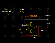
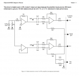
The circuit says: "This circuit is helpful even in BTL mode if noise is an issue because the amplifier inputs are two SE inputs
referenced to ground. All 5k6 resistors should be with 1% or 0.1% tolerance for best performance." and no, I didn't know that it also inverted the signal
as far as I can tell the Designers Manual doesn't mention inverting the signal but I guess they weren't targeting it at people with so little knowledge Thanks gentlemen
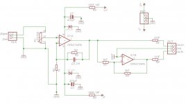
How about this?
You will see the OPA is now a 2134, that's because I couldn't find a NE5532 in Eagle, but I was wondering if the 2134 would work just as well, as I already have some, if not that's fine to.
My next challenge will be working out how I'm going to fit this in the Sub as it wasn't designed with this in mind
Many thanks
Attachments
Last edited:
Yep, 2134 will be fine. The 1nf capacitor can be MKP, but a Polyester wouldn't make any difference in that position, & for bass !
This time you've copied my circuit correctly
Excellent thanks, now I'll see if I can get the PCB laid out so it works.
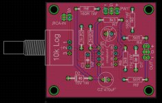
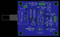
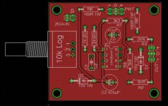
Hows this look?
I did find working out how to wire the pot a bit confusing!!! I found trying to work out which was the input & ground from the data sheet baffling, I figure once I get it, I can work it out & put the pot on the other side of the board if necessary
I assume if it was a linear pot it wouldn't matter but with a log pot it should matter.
Attachments
Last edited:
Nice looking boards
From above with the pot base sat flat on a table for eg, if you look down @ the pot from the shaft/knob position, the input would go on the right pin & the output on the middle pin & the ground on the left pin.
It makes a difference for both, but a Log would be better.
I did find working out how to wire the pot a bit confusing!!! I found trying to work out which was the input & ground from the data sheet baffling,
From above with the pot base sat flat on a table for eg, if you look down @ the pot from the shaft/knob position, the input would go on the right pin & the output on the middle pin & the ground on the left pin.
I assume if it was a linear pot it wouldn't matter but with a log pot it should matter.
It makes a difference for both, but a Log would be better.
Nice looking boards
From above with the pot base sat flat on a table for eg, if you look down @ the pot from the shaft/knob position, the input would go on the right pin & the output on the middle pin & the ground on the left pin.
If I'm reading your words correctly it means I have got the pot around the wrong way which will mean I either need to change the board or put the pot on the bottom of the board
The Bourns data sheet really gives an amateur very little to go on, I was thrown off by the CW/CCW thing & couldn't find out if that was just the way the knob turns! or the wiring was done, or what, the only reference in the data sheet is attached. I have wired pots before, I searched the web but couldn't find a definitive answer. Why cant they just go 1= In 2=Out 3=Gnd or something like that.
Attachments
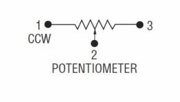
I thought the pot looked like a Bourns, as i've used them a lot over the years = nice Yeah, i know what you mean about CCW/CW, but you soon get the hang of it CCW = counter clockwise & CW = clockwise. Of course it depends whether you're looking from the front, or the back Interestingly, Bourns describe some models differently ?
Here it's just 1/2/3 http://www.farnell.com/datasheets/1790255.pdf
Here it's 1/2/3 & CCW/2/CW http://www.farnell.com/datasheets/1719387.pdf
Yeah, i know what you mean about CCW/CW, but you soon get the hang of it CCW = counter clockwise & CW = clockwise. Of course it depends whether you're looking from the front, or the back Interestingly, Bourns describe some models differently ?Here it's just 1/2/3 http://www.farnell.com/datasheets/1790255.pdf
Here it's 1/2/3 & CCW/2/CW http://www.farnell.com/datasheets/1719387.pdf
- Status
- This old topic is closed. If you want to reopen this topic, contact a moderator using the "Report Post" button.
- Home
- Source & Line
- Analog Line Level
- Suggestions Requested for Mini Buffer Preamp