Hi,
First: I am a complete newbie, so please be critical but friendly.")
I am building a Najda DSP box, but would like to have balanced outputs. So I have tried to draw a PCB with 8 input channels and 8 Neutrik XLR outputs.
The schematics are mostly based on a standard variant from the THAT 1646 datasheet. I couldn´t find bipolar capacitors with radial connections in Eagle, so I have used a polarised variant in the diagram and board.
I also received the schematic from a friendly diyaudio-er, who has built similar boards earler. I will update with his alias later if he prefers, so credit can be given properly.
Here is the schematic:
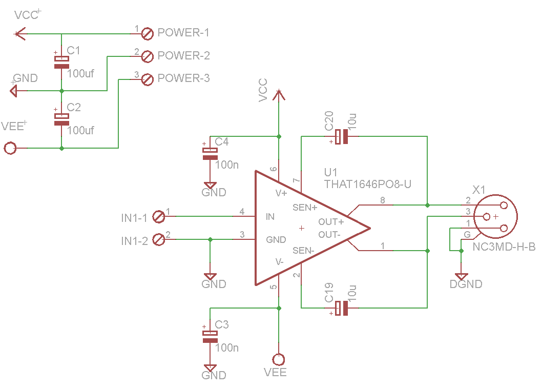
The bit around the THAT1646 is repeated 8 times.
The main thing I have tried to do is to avoid the Pin 1 problem by tying it directly to a separate ground plane. Analogue ground and digital ground is not connected at the board, but will be connected somewhere else on the chassis.
Note that C20 and C19 should be non-polarised/bipolar caps (as mentioned above).
Questions:
1. Any thing in particular I should modify? Errors/improvements?
2. Do I have C3 the wrong way around?
3. Is it OK with 2x100uf capacitors on the power input? (keeping in mind I have 8 chips on the board)
4. Do I have C2 the wrong way around?
5. Should I use regulators on such a circuit - if so, what do you recommend? This is a one-off project, so I´m not looking for the most cost-effective solution, but rather want to know I have gotten a "blameless" part in the audio-chain.
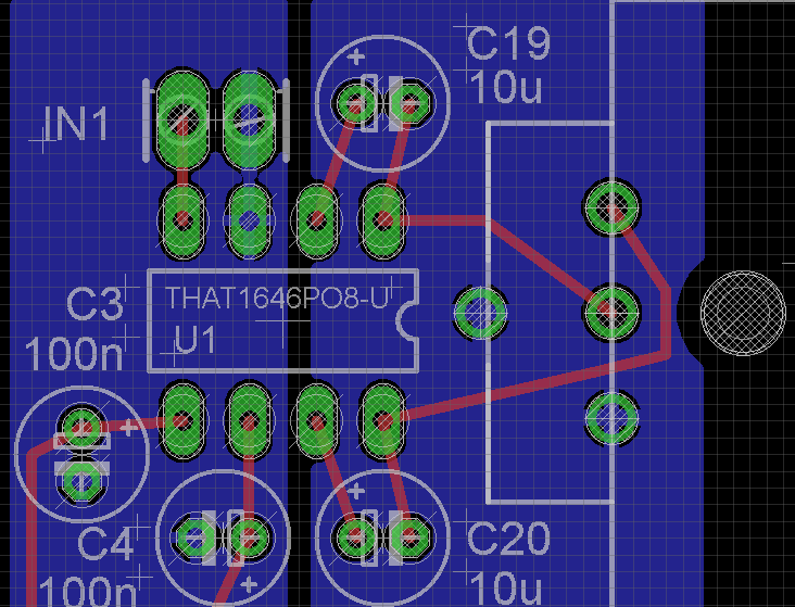
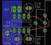
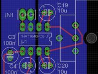
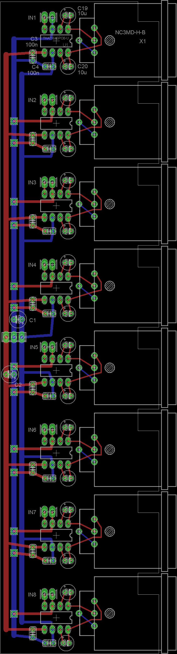
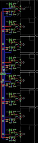
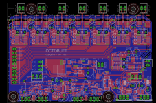
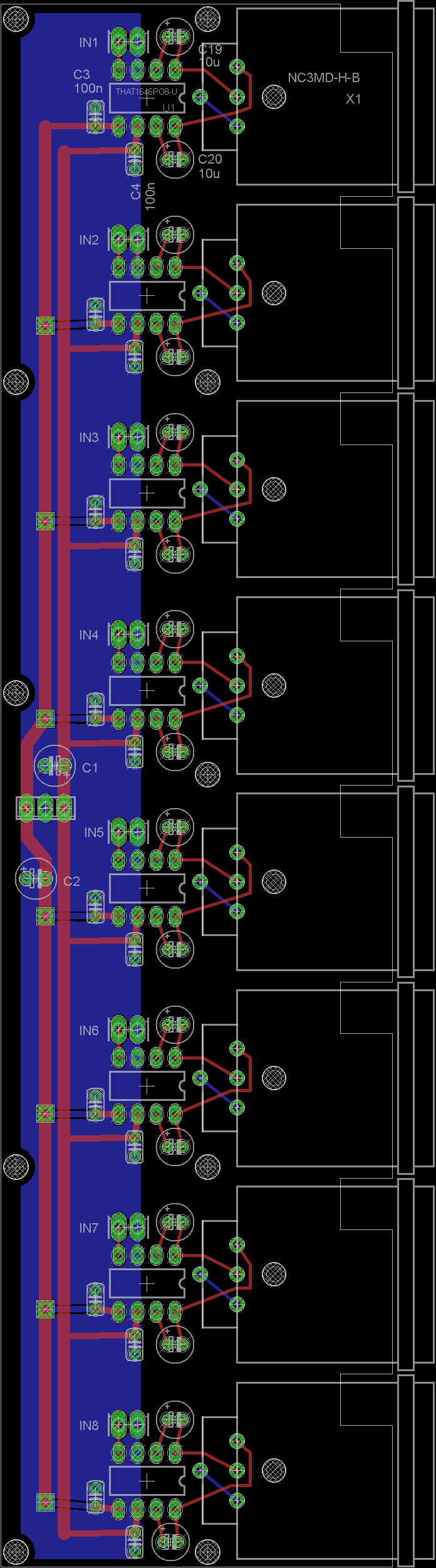
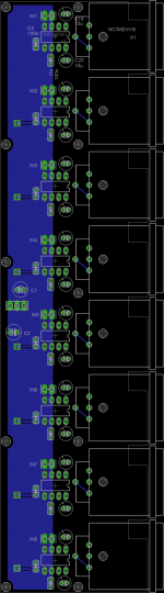
And here is the board:
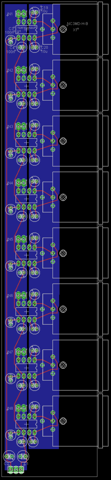
I have run all the power and signal traces on the top layer. There are two ground fills on the bottom layer - analogue ground for power and analogue signal and "shield" (DGND on the schematic) to act as an extension of the XLR shield and tie together G and Pin 1 on the XLR.
Does this look like a reasonable layout? I know that the connectors are small, but I have used them before (Phoenix 2.54 pitch) and they work well for me.
The Najda is powered by +/- 12V, and I would like to use the same power supply for this one. Maximum output from the Najda is +/- 6V (15.5dbV). Would these chips be able to turn these signals into balanced without clipping with the same power supply?
First: I am a complete newbie, so please be critical but friendly.
I am building a Najda DSP box, but would like to have balanced outputs. So I have tried to draw a PCB with 8 input channels and 8 Neutrik XLR outputs.
The schematics are mostly based on a standard variant from the THAT 1646 datasheet. I couldn´t find bipolar capacitors with radial connections in Eagle, so I have used a polarised variant in the diagram and board.
I also received the schematic from a friendly diyaudio-er, who has built similar boards earler. I will update with his alias later if he prefers, so credit can be given properly.
Here is the schematic:
The bit around the THAT1646 is repeated 8 times.
The main thing I have tried to do is to avoid the Pin 1 problem by tying it directly to a separate ground plane. Analogue ground and digital ground is not connected at the board, but will be connected somewhere else on the chassis.
Note that C20 and C19 should be non-polarised/bipolar caps (as mentioned above).
Questions:
1. Any thing in particular I should modify? Errors/improvements?
2. Do I have C3 the wrong way around?
3. Is it OK with 2x100uf capacitors on the power input? (keeping in mind I have 8 chips on the board)
4. Do I have C2 the wrong way around?
5. Should I use regulators on such a circuit - if so, what do you recommend? This is a one-off project, so I´m not looking for the most cost-effective solution, but rather want to know I have gotten a "blameless" part in the audio-chain.
And here is the board:
I have run all the power and signal traces on the top layer. There are two ground fills on the bottom layer - analogue ground for power and analogue signal and "shield" (DGND on the schematic) to act as an extension of the XLR shield and tie together G and Pin 1 on the XLR.
Does this look like a reasonable layout? I know that the connectors are small, but I have used them before (Phoenix 2.54 pitch) and they work well for me.
The Najda is powered by +/- 12V, and I would like to use the same power supply for this one. Maximum output from the Najda is +/- 6V (15.5dbV). Would these chips be able to turn these signals into balanced without clipping with the same power supply?
Attachments
Two comments on the circuit:
1 - it is good practise to use a resistor of 20-50 ohms in series with each signal output between the chip and the connector, to isolate the opamp from capacitive loads like cables, to avoid instabilities.
2 - pin 1 of the XLR should be connected to the case/chassis ONLY, not to any ground of the circuitry. This is critical for hum/buzz free operation!
Jan
Thanks Jan,
1: Is that necessary also with the THAT 1646? The datasheet says: The devices are stable into any capacitive load, and the maximum capacitance is limited only by slew rate and frequency response considerations.
2: I figured that the connector will be clamped to the aluminium chassis, thus connecting G with the chassis, and so shorting pin 1 and G on the connector at the PCB would be similar to having a wire from pin 1 to the chassis. The ground plane on the right is not connected to anything except Pin 1 and G on the XLR connectors. Shouldn´t that give the same effect? I hoped I would be able to do it on the PCB instead of having wires to the back panel, as this will make a complicated build. Does it make any sense?
Thanks TheShaman. It does seem like the author connects pin1 to GND though. I have understood that AES48 specifies that pin1 should be shorted to the shield at the connector and that one should tie this together with gnd someplace else, say at a star grounding spot at the other end of the chassis (the chassis connects them). Or did I interpret this incorrectly?
Thanks Jan,
1: Is that necessary also with the THAT 1646? The datasheet says: The devices are stable into any capacitive load, and the maximum capacitance is limited only by slew rate and frequency response considerations.
2: I figured that the connector will be clamped to the aluminium chassis, thus connecting G with the chassis, and so shorting pin 1 and G on the connector at the PCB would be similar to having a wire from pin 1 to the chassis. The ground plane on the right is not connected to anything except Pin 1 and G on the XLR connectors. Shouldn´t that give the same effect? I hoped I would be able to do it on the PCB instead of having wires to the back panel, as this will make a complicated build. Does it make any sense?
1 - OK, if THAT says so, it's OK I guess.
2 - I see in the schematic a connection between 'DGND' and pin 1. That's a no-no.
In this case where you have the connector on the PCB, I would put a solder lug on the connector mounting screw and connect that to pin 1, and nowhere else.
The idea is to keep the connection very short to avoid bringing an antenna into the case, and separate from anything else. This connection should make the case an extension of the cable shield.
Jan
Jan,
Thanks again. So, what you are suggesting is something like this, which is from Hypex´s appnote on the pin 1 issue:
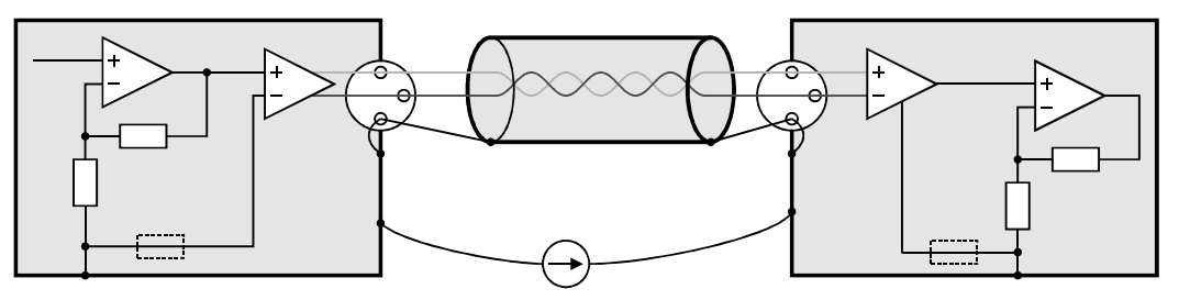
Instead of doing a DGND reference, I could do like this:
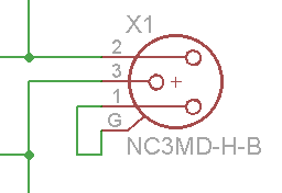
i.e. just shorting pin 1 and G on the connector.
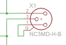
It would look like this on the PCB:

Instead of like this, which was what I thought originally:
Because my chassis needs to have the back panel come on after I put on the and bottom, I need to have everything connected properly before I put the back panel on. Rather odd design, but it was expensive, so I´m rather stuck with it. So would shorting G and pin 1 through a short trace do the trick? This is literally ON the connector (you see the footprint on the PCB drawing).
BTW: DGND was just a name I used because I didn´t know Eagle very well. I could just as well had called it Shield - would probably have been more informative. The original idea was to bring the shield all the way back to the chip, including the feedback traces (C19 and C20). Perhaps it doesn´t make any sense when there is a shield around the whole thing (chassis) anyway.
Thanks again. So, what you are suggesting is something like this, which is from Hypex´s appnote on the pin 1 issue:
Instead of doing a DGND reference, I could do like this:
i.e. just shorting pin 1 and G on the connector.
It would look like this on the PCB:
Instead of like this, which was what I thought originally:
Because my chassis needs to have the back panel come on after I put on the and bottom, I need to have everything connected properly before I put the back panel on. Rather odd design, but it was expensive, so I´m rather stuck with it. So would shorting G and pin 1 through a short trace do the trick? This is literally ON the connector (you see the footprint on the PCB drawing).
BTW: DGND was just a name I used because I didn´t know Eagle very well. I could just as well had called it Shield - would probably have been more informative. The original idea was to bring the shield all the way back to the chip, including the feedback traces (C19 and C20). Perhaps it doesn´t make any sense when there is a shield around the whole thing (chassis) anyway.
Attachments

Last edited:
It looks alright, I don't really see an issue using that ground plane and bonding it to the chassis directly since you've shown a separate plane to the circuit ground.
I have a very similar board I designed, it's on its way to me now, but I am using THAT1606 and chassis mount XLRs. I only bring out the hot and cold lines from the PCB, knowing that I'll simply connect pin 1 on all XLRs directly to the chassis. Ultimately, the chassis will connect to circuit ground, but only at one point, the PSU. I will have spares of this board BTW if you're interested, it does include relay muting and a headphone amplifier but you can just leave those parts off, but it does require small SMD soldering.
On your design I would be tempted to thicken the power supply traces up, even though the THAT1646 has excellent PSRR, it's never ideal to have the devices up-stream fed from power lines already modulated by downstream stages. Also, you might consider changing your bypass capacitor silkscreen as they look like electrolytics, in Eagle try resistor - C-EU then the top symbol, then you could use a 2.5mm pitch leaded MLCC and the appearance will closely match the silkscreen
The 2 x 100uF is probably a good idea. Make sure you can get ones with the required voltage rating in that size though, but actually 22uF would be plenty. I would consider moving them to the middle of the board though.
Good luck with it!
Last edited:
Possibly add a small ferrite in series with each leg going off board (Wurth make some reasonable parts in hand solderable SMT) to try to keep the mobile phones out.
Would it benefit from a little series resistance (And some transient protection) just to improve immunity to P48 accidents?
Also some of those tracks are at weird angles, snap to 45/90 is usually considered to keep things looking tidy.
Regards, Dan.
Would it benefit from a little series resistance (And some transient protection) just to improve immunity to P48 accidents?
Also some of those tracks are at weird angles, snap to 45/90 is usually considered to keep things looking tidy.
Regards, Dan.
I' personally advise against adding any series resistance since the internal resistors are extremely closely matched. Anything you add will not be so close and hence degrade the common mode balance, even 1% resistors will degrade it significantly. Inductors with low DC resistance are ok to add and for protection, the datasheet shows a scheme with diodes, depends how likely it is to be used by others!
Also ensure your previous stage can drive the 5K input impedance of these chips, it's not terribly low but some stages won't perform optimally with this, or if you start to parallel things with it.
Also ensure your previous stage can drive the 5K input impedance of these chips, it's not terribly low but some stages won't perform optimally with this, or if you start to parallel things with it.
Jan - I reread your post, the sentence about a solder lug on the mounting screw. Wont I do exactly the same in my "without plane" example above, except using a trace instead of a wire?
Yes, sorry for the delay, that should be OK as well. The main points are: keep it VERY short, and don't connect the pin 1 & connector case to anything else but the enclosure. The screen on the cable acts then as a sort of tunnel between the two equipment chassis.
Now, you can bet your sweet whatever that there will be a ground current through the screen. So the 2nd requirement on the cable is that the two signal wires (hot & cold, to pins 2 and 3) are nicely symmetrical with respect to the screen, ideally equal cap to the screen, equal distance etc.That way, the induced junk with be equal in each wire, and the balanced receiver will subtract the two and cancel them.
Bruno has his own cable manufactured, but I don't think it is available outside Europe. But the usual suspects like Belden and van Damme surely have a good quality screened balanced cable.
Jan
Thanks Dr_EM!
I tried to make the tracks wider, but it ended up complex running them under the chip like I had done, so I had to redo the power supply thing. I tried with ground pours, but it ended up difficult to see how well the ground could return, so I made a "star ground" track as well. Needed to use vias, but I made them big, so I guess they shouldn´t be a bottleneck.
I also changed the capacitor as you suggested. Do you know if there is a non-polarized electrolytic radial cap (i mean barrel with two legs on bottom) in Eagle? I Can´t find it at least.
Can you please review the revised version? I have stuck with a simple connection between pin 1 and G (G being barrel of XLR).
I would love to see your board layout, but I don´t think I can use it, since with the chassis I got I need to mount everything on PCBs and then stick the back panel on last. (Very bad design - it requires me to be very precise when positioning the components otherwise the panel won´t fit).
Attachments
The thicker traces look good but I would really recommend still using a ground plane. You have a 2 layer board here and it's common practice to make one layer (I use the bottom) a ground plane, which you may interrupt with short traces if essential. The lower impedance your ground plane, the more accurate the ground reference for each device is. Remember that PSRR can't help you here since the output signal is formed by referencing it to ground, so that (hypothetical) 1mV potential difference across a ground connection appears directly on the output as 1mV of noise!
I've attached my design. You can see on it that the bottom layer is almost uninterrupted ground pour and that SMT devices requiring a ground connection have vias (usually several) linking them to that plane as close to the device as possible. The THAT1606 has several ground pins around it and the polygon pour on the top layer also helps carry heat away. Most of the bottom half is the headphone amplifier, voltage regulation and relay control.
I've never noticed a non-polar cap in Eagle tbh, I did look earlier too but couldn't see any. Bound to be a library online for them, or you could get stuck in with making custom libraries in Eagle, it's far from intuitive
Attachments
Everybody - thanks a lot for your help!
@Dr_EM
Ok, I have tried to bring back the ground plane.
Yeah, I tried making custom parts in Eagle (thought of doing this thing with a Neutrik Ethercon to save rear panel space, but the interface drove me nuts, so I gave up and took a safer route).
@dmills:
I will keep cables from this unit very short. Is it still necessary to use ferrite beads?
I will google how to snap to 45/90. Too late to fix it now, but will look at it in the next iteration. Thanks for the tip.
Both: I will only use this in my home, with short cables directly to an amp. I don´t foresee anybody plugging anything into it that doesn´t belong there. I suppose I don´t need any protection features then?
@Jan: I will keep quality of cable in mind.
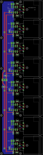
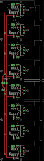
Both layers:
Top layer:

Bottom layer:

Is it getting closer to a good layout?
Oh, one thing: I didn´t get an answer to whether or not I should use regulators on this thing. The Najda DSP, which will be feeding this board has CS3318 (volume control chip with single ended output). The Najda board takes +/- 12V, and regulates this down to 8.5V for the CS3318.
I suppose this regulation downwards limits the output voltage for the Najda. Aparently the maximum output is 6VRMS.
I was hoping to use the same power supply to drive the Najda and the output board. So +/- 12V it is. Does it make sense for me to regulate this voltage down to +/- 8.5V as well, and hopefully get less noise?
Also - any recommendation for the bypass caps?
@Dr_EM
Ok, I have tried to bring back the ground plane.
Yeah, I tried making custom parts in Eagle (thought of doing this thing with a Neutrik Ethercon to save rear panel space, but the interface drove me nuts, so I gave up and took a safer route).
@dmills:
I will keep cables from this unit very short. Is it still necessary to use ferrite beads?
I will google how to snap to 45/90. Too late to fix it now, but will look at it in the next iteration. Thanks for the tip.
Both: I will only use this in my home, with short cables directly to an amp. I don´t foresee anybody plugging anything into it that doesn´t belong there. I suppose I don´t need any protection features then?
@Jan: I will keep quality of cable in mind.
Both layers:
Top layer:
Bottom layer:
Is it getting closer to a good layout?
Oh, one thing: I didn´t get an answer to whether or not I should use regulators on this thing. The Najda DSP, which will be feeding this board has CS3318 (volume control chip with single ended output). The Najda board takes +/- 12V, and regulates this down to 8.5V for the CS3318.
I suppose this regulation downwards limits the output voltage for the Najda. Aparently the maximum output is 6VRMS.
I was hoping to use the same power supply to drive the Najda and the output board. So +/- 12V it is. Does it make sense for me to regulate this voltage down to +/- 8.5V as well, and hopefully get less noise?
Also - any recommendation for the bypass caps?
Attachments
Looks good to me. It's hard to tell which pins go to the ground plane on the image but I assume all the ones which need to do.
The ferrites I think are optional, unlikely to be required in a domestic setting, but shouldn't do any harm either. If it's only you using it I don't see much point in adding the over-voltage protection diodes.
My THAT1606 board also follows on from a CS3318! In my case, both boards have local regulation. The CS3318 regulates down to +/-8.8V and the THAT1606 board will regulate down to +/-10V or so, both being fed from smoothed but unregulated supplies of +/-14V or so. The increased voltage on the THAT1606 board is only really for the headphone amplifier. BTW, I should give credit for that headphone amplifier, the silkscreen is supposed to reflect this too and needs updating, it is from our member Bonsai and can be seen here.
For your application I'd run the board from the +/-12V supplies, assuming those are clean supplies. If not, you will be better off using the regulated +/-8.5V supplies but be aware of increased thermal dissipation in those regulators. Bypass caps, any 100nF ceramic (2.54mm pitch) should work fine
Thanks again. All the ground pins are connected to the ground plane.
I am not sure which power supply I will use. Most people use "standard" power supplies with the Najda, which has regulators on board. The Najda is reported to have low noise outputs. I am thinking it doesn´t make sense to go overboard on the power supply side if I can add regulators to my output board instead, and rather use a MeanWell power +/-12, 5V supply - at least have the option to do so.
I think I understand the prinsiple of the LM337 and LM317 regulators, but I´m not qualified to determine the implementation. There are high stability variants, tracking variants etc. Any hints on which schematic to go with to give good performance in such an application? I guess 8.5v is because 3v drop is required from 12v right?
If I use regulators, do I still need the 100uf caps at the power connectors?
BTW: I saw your other project in another thread - the CS3318 board. Neat! I have looked for one for ages. Now I found a DSP with digitally controlled analogue outputs, so it kind of solves it for me, but so far I´ve used the digital volume control of the Opus DAC from twisted pear audio via SPI (Arduino). Once I was able to talk to the VM8741 chips it has worked flawlessly, but having a CS3318 in between solves two things for me: It can add some gain to maximize bit resolution in the DSP (I use dipole EQ in my Orions which steals some DSP headroom), and I can experiment with high efficiency speakers later (I am imagining that a compression driver would expose noise in my system - making it more than audible with only digital volume control, and I also fear for my hearing if the DSP should crash and send 0dbFS signals directly to the amps). I have been thinking of using a computer and sound card, but still haven´t been able to find a way to make it livingroom-friendly with multiple digital inputs, remote control etc).
The thicker traces look good but I would really recommend still using a ground plane. You have a 2 layer board here and it's common practice to make one layer (I use the bottom) a ground plane, which you may interrupt with short traces if essential. The lower impedance your ground plane, the more accurate the ground reference for each device is. Remember that PSRR can't help you here since the output signal is formed by referencing it to ground, so that (hypothetical) 1mV potential difference across a ground connection appears directly on the output as 1mV of noise!
I've attached my design. You can see on it that the bottom layer is almost uninterrupted ground pour and that SMT devices requiring a ground connection have vias (usually several) linking them to that plane as close to the device as possible. The THAT1606 has several ground pins around it and the polygon pour on the top layer also helps carry heat away. Most of the bottom half is the headphone amplifier, voltage regulation and relay control.
I've never noticed a non-polar cap in Eagle tbh, I did look earlier too but couldn't see any. Bound to be a library online for them, or you could get stuck in with making custom libraries in Eagle, it's far from intuitive
Hi, one short question
, the Datasheet of the THAT1606 recommend to use one resitor and one capacitor at the sens input pins. It seems you add two capacitors instead.. why ?- Status
- This old topic is closed. If you want to reopen this topic, contact a moderator using the "Report Post" button.
- Home
- Source & Line
- Analog Line Level
- THAT 1646 PCB - help me review please