Hello everybody!
It's been awhile I've been part of diyAudio only in reading mode, and I definitely have found some really interesting stuff here!
This is my first thread, so sorry for any missuse...
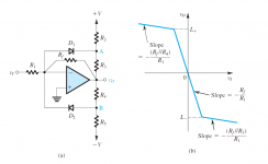
By reading Sedra/Smith microelectronics book I have found this interesting compressor/limiter circuit that I have never seen before anywhere.
Any one have any thoughts about that??
It has some drawbacks of dependence between threshold and compression level... but it's stupidly simpler compared with any other compressor design (even compared with LDR!)
Thank you all!
It's been awhile I've been part of diyAudio only in reading mode, and I definitely have found some really interesting stuff here!
This is my first thread, so sorry for any missuse...
By reading Sedra/Smith microelectronics book I have found this interesting compressor/limiter circuit that I have never seen before anywhere.
Any one have any thoughts about that??
It has some drawbacks of dependence between threshold and compression level... but it's stupidly simpler compared with any other compressor design (even compared with LDR!)
Thank you all!
Attachments
")
I'm still amazed about the simplicity of this design.
As I've been a while looking for a simple guitar/bass compressor.
The idea of a interdependence of the threshold voltage and the compression rate is starting to look interesting for an instrument compressor.
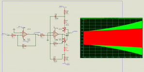
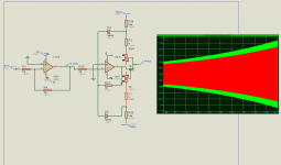
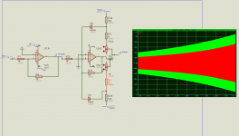
After a lot of tweaking with the equations, this is what I came with.
The minimum compression is ~ 1:2 (actually is 1:1.88) with a threshold of 2.4V.
The maximum compression is 1:11 with a threshold of 0.86V
In the attachment is the simulation of my circuit for maximum, minimum and medium compression.
As I've been a while looking for a simple guitar/bass compressor.
The idea of a interdependence of the threshold voltage and the compression rate is starting to look interesting for an instrument compressor.
After a lot of tweaking with the equations, this is what I came with.
The minimum compression is ~ 1:2 (actually is 1:1.88) with a threshold of 2.4V.
The maximum compression is 1:11 with a threshold of 0.86V
In the attachment is the simulation of my circuit for maximum, minimum and medium compression.
Attachments
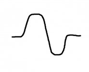
If you don't want significant distortion, you probably won't like how that circuit sounds. It's not a compressor in the truest sense of the word.
More of a soft clip with individually adjustable levels for - and + It will do something like this to the signal.
Attachments
@ Mark Johnson
@ poynt99
Thanks for the tips about SSM and Orange Squeezer, I already knew about them.
but SSM2167 can handle to low voltage input to me...
And I was actually studing Orange Squeezer to make my own compressor when I found this circuit.
But actually this circuit ain't exactly a clipper IMO, couse the diodes aren't in the audio path, only in the feedback circuit of the op amp.
By what I see in the circuit the diodes works kind of shunting the feedback resistor changing the op amp gain after the threshold voltage is reached. But by resistors R3 and R4 you can even set the gain after the threshold to be the same as before the threshold
Just a little update after some tests and thougts
You guys were right, my bad...
Indeed it doesn't works as a compressor as I thougth... becouse it compressonly the part of the wave above the threshold... almost a softcliper, but really really soft.
As soon as I can I will check the amount of distortion introduced by the circuit.
I still want to build it and test, as it still may work as a signal compressor, and distorion ain't exactly a problem in instruments.
It may still worth a try.
- Status
- This old topic is closed. If you want to reopen this topic, contact a moderator using the "Report Post" button.
- Home
- Source & Line
- Analog Line Level
- Compressor design - Sedra/Smith book