Hi,
This is my first 'proper' posting on this forum. Apologies if this is in the wrong section.
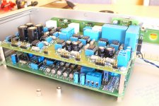
Here's my latest build...
I'll post more photos as the build proceeds. Sorry about the blurriness - I'll post some better photos later.
Dave.
This is my first 'proper' posting on this forum. Apologies if this is in the wrong section.
Here's my latest build...
I'll post more photos as the build proceeds. Sorry about the blurriness - I'll post some better photos later.
Dave.
Attachments
More info...
Hi,
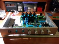
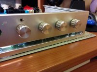
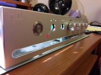
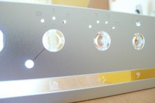
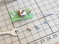
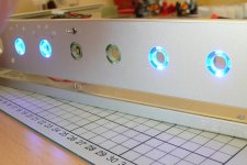
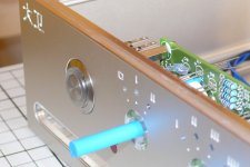
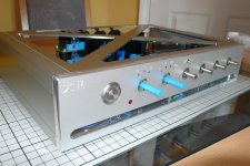
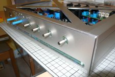
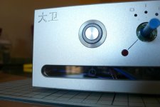
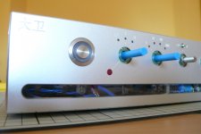
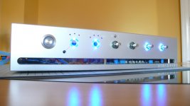
Forgot to mention: I'm building this preamp for my father-in-law who is Chinese, so all the engravings have to be in Chinese. I am using Front Panel Designer to do the panels and I am trying to achieve a screwless look. The tiny toggle switch on the front panel is the tone defeat and I re-made the rotary switch PCB to introduce some cool lighting effects. The long acrylic panel show the control ledgends. The knobs will have illumination around them. The red LLLL LED is not lit - it's just the desk light illuminating it from behind
Dave.
Hi,
Forgot to mention: I'm building this preamp for my father-in-law who is Chinese, so all the engravings have to be in Chinese. I am using Front Panel Designer to do the panels and I am trying to achieve a screwless look. The tiny toggle switch on the front panel is the tone defeat and I re-made the rotary switch PCB to introduce some cool lighting effects. The long acrylic panel show the control ledgends. The knobs will have illumination around them. The red LLLL LED is not lit - it's just the desk light illuminating it from behind
Dave.
Attachments
Nice! I like the chassis.
I have been studying this pre-amplifier with the possibility of building it. So I look forward to following your build.
Hi Dennis,
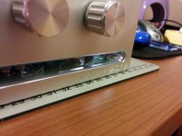
I'm quite happy to explain further how the chassis goes together. But, be warned - it's expensive. The panels you see in these photos cost about €700!
Dave.
Hi Dennis,
But, be warned - it's expensive. The panels you see in these photos cost about €700!
Dave.
Wow! That is expensive. Fortunately, I am thinking of a DIY chassis. It really is the internals that has my focus. I have bought the 3 part online Elector articles. I also have the last edition of the authors book. The cost of the PCB's seem reasonable.
I find following others projects gives me confidence and motivation. Thanks for posting this.
If you'd like, I have made the rotary switch PCB better - the switch alingment now makes sense and I added provision for LED illumination for each selection. All selections will light, but the selected one will be brighter. (Tried it out on breadboard, I haven't powered the real thing yet
). I have the gerber files for the new PCB...I will post more photos this weekend as I have to disassemble the amp to do some fine filing - ha ha!
Dave.
PCBs
Hi,
Here are the photos I promised (I will have to load them slowly across more posts)...
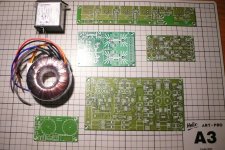
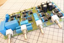
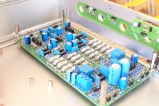
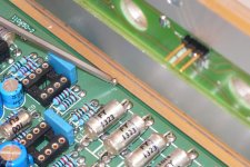
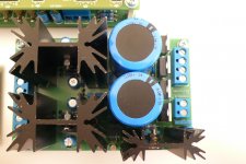
I started the build back in September last year with the boards from Elektor and decided on a layout. It took some time to populate the boards and design the panels.
More to come...
Hi,
Here are the photos I promised (I will have to load them slowly across more posts)...
I started the build back in September last year with the boards from Elektor and decided on a layout. It took some time to populate the boards and design the panels.
More to come...
Attachments
-
 006 Initial Layout.JPG737.5 KB · Views: 1,610
 -
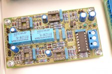
 018 Phono PCB.JPG701.4 KB · Views: 899
 -
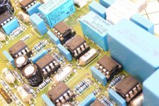
 023 Phono PCB Resistors.JPG698.2 KB · Views: 680
 -
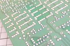 026 Phono PCB Soldering.JPG770.2 KB · Views: 478
 -
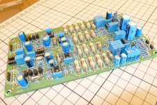
 029 Line-In PCB Pots.JPG672.8 KB · Views: 594
 -
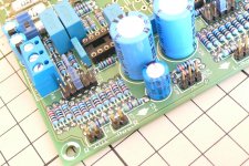
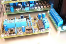
 028 Line-In PCB Close-Up.JPG670.3 KB · Views: 593
 -
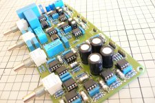 030 Line-In PCB.JPG654.6 KB · Views: 552
 -
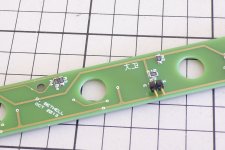
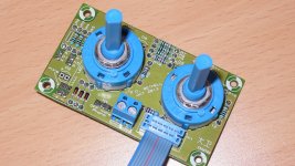 031 Re-Designed Rotary Switch PCB.JPG797.3 KB · Views: 581
Mechanical Assembly 1
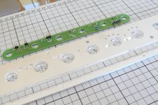
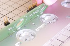
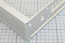
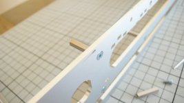
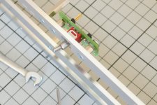
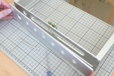
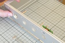
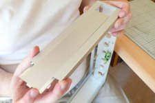
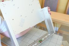
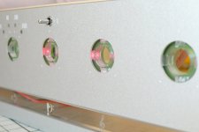
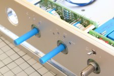
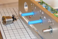
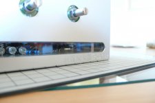
Here you can see the special light conduits I designed for the pots (made by Schaeffer) and how the plastic parts fit into the front panel. the front panel actually consists of 2 panels in order to produce the 'no visible screws' look. I also designed an illumination PCB to fit behind the light conduits. the Bass and Treble pots will glow bue unless they're switched to 'Tone Defeat', in which case they'll glow red to show they're not in use. I remembered to mill cut-outs where the PCB conatcts meet the front panel.
More construction photos to follow...
Dave.
Attachments
-
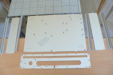 034 Base, Sides, Corner Extrusions and Front Inner Panels.JPG541.2 KB · Views: 898
 -
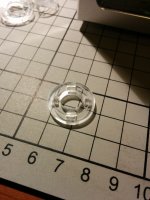 035 Light Conduit for Pots.jpg573.3 KB · Views: 848
 -
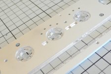 036 Plastic Parts Fitted to Front Outer Panel.JPG701.3 KB · Views: 799
 -
 039 Long Panel.JPG599.7 KB · Views: 756
 -
 040 Illmination PCB Aligned with Front Panel.JPG646.1 KB · Views: 711
 -
 042 Showing Alignment.JPG648.5 KB · Views: 232
 -
 044 Illumination PCB Detail.JPG668.1 KB · Views: 249
 -
 045 Method of Assembly - Sides.JPG592.4 KB · Views: 224
 -
 046 Method of Assembly - Top Extrusions.JPG626.3 KB · Views: 244
 -
 050 Method of Assembly - Detail Showing Side Panel.JPG680.1 KB · Views: 254
Your build is a work of art! I built this when it first appeared in Elektor and was very impressed. (got me hooked on DIY audio) I was a bit surprised though, that more people did build this as it is a first rate piece of equipment.
Me
Ha ha! My wife said that the other day! I always use blue as my theme because you can get quite a few parts in that colour. It was tricky trying to find parts that matched the original specs but in blue
I noticed that the original PCBs seemed to have provision for boxed polyprop caps, so I searched far and wide to find the originals. They added quite a bit of height to the PCB but it all fits into a 340 x 200 x 70mm case.
Last edited:
Mechanical Assembly 2
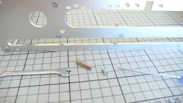
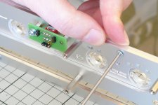
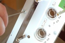
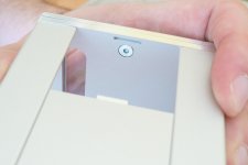
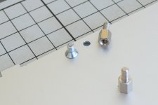
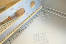
These photos show how the PCB pillars for the new rotary switch PCB and the tone defeat switch PCB are fixed to the inner front panel. The last few show how the two front panels are sandwiched together to hide the fixing screws. The screws used to fix the two panels together have been cut down to size.
Dave.
Attachments
-
 051 Method of Assembly - 20mm PCB Pillars for Rotary Switch PCB.JPG798.1 KB · Views: 206
 -
 052 Method of Assembly - 20mm Pillar fitted to Front Inner Panel.JPG710.8 KB · Views: 122
 -
 054 Method of Assembly - Tone Defeat Switch PCB & Parts.jpg188.1 KB · Views: 186
 -
 056 Method of Assembly - Tone Defeat Switch Fitted to Front Inner Panel.JPG690.5 KB · Views: 188
 -
 057 Method of Assembly - Aligning Front Outer and Inner Panels.JPG718.7 KB · Views: 140
 -
 058 Method of Assembly - Close-Up.JPG655.3 KB · Views: 155
 -
 060 Method of Assembly - Fitting Front Outer Panel.JPG728 KB · Views: 143
 -
 061 Method of Assembly - Front Outer Panel Aligned.JPG743 KB · Views: 134
 -
 062 Method of Assembly - Fixing front Outer Panel with Cut-Down Screws.JPG663.9 KB · Views: 191
 -
 063 Method of Assembly - Detail.JPG551.8 KB · Views: 231
Last edited:
Mechanical Assembly 3
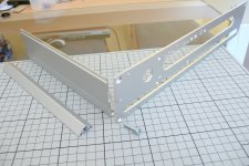
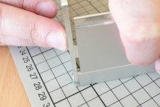
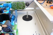
These photos show how the sides slot in with their 'tongue-and-slot' ends. I was going to use Schaeffer's corner brackets to stop the top and bottom of the case from flexing, but I didn't have enough room in the case. So I designed the panels with little tongues and slots to prevent any flexing of the panels.
Here you can also see how the illumination PCB fits and how it illuminates. Those red LEDs are a bit dim - they'll need replacing
Dave.
Attachments
-
 065 Method of Assembly - Slotting in Sides.JPG617.8 KB · Views: 229
 -
 066 Method of Assembly - Detail.JPG555.6 KB · Views: 148
 -
 071 Method of Assembly - Rotary Switch PCB Fixing Points.JPG707 KB · Views: 134
 -
 073 Method of Assembly - Base Panel PCB Pillars & Cut-Down Screws.JPG636.6 KB · Views: 123
 -
 077 Method of Assembly - Slotting In Base Panel.JPG691.4 KB · Views: 116
 -
 078 Method of Assembly - Base Panel Detail.JPG633.5 KB · Views: 119
 -
 079 Method of Assembly - Fitting Illumination PCB.JPG673.2 KB · Views: 156
 -
 081 Method of Assembly - Testing Illumination PCB with a Battery Pack.JPG648.8 KB · Views: 214
 -
 082 Method of Assembly - Blue LEDs.JPG736.6 KB · Views: 215
 -
 083 Method of Assembly - Tone Defeated Red LEDs a bit Dim!.JPG626.1 KB · Views: 168
Mechanical Assembly 4
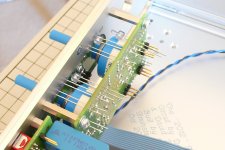
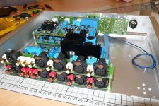
Here I am fitting the main PCBs into the case. There were some scary moments when I thought my maths had gone wrong - the pots didn't line up with the front panel holes until I realised that I still had the screws done up tight. There was enough play in the PCB holes to align everything Remember that Front Panel Designer is a 2D tool and my brain had to think in 3D There is a screw missing on the tone Defeat PCB because the big capacitor on the line-in PCB got in the way - I didn't see that one in my 3D visualisation!
The Log-Law Level LED PCB seems like a lot to light one LED, but considering the amount I have spent on this project it didn't seem fair to leave it out.
Dave.
Here I am fitting the main PCBs into the case. There were some scary moments when I thought my maths had gone wrong - the pots didn't line up with the front panel holes until I realised that I still had the screws done up tight. There was enough play in the PCB holes to align everything
Remember that Front Panel Designer is a 2D tool and my brain had to think in 3D There is a screw missing on the tone Defeat PCB because the big capacitor on the line-in PCB got in the way - I didn't see that one in my 3D visualisation! The Log-Law Level LED PCB seems like a lot to light one LED, but considering the amount I have spent on this project it didn't seem fair to leave it out.
Dave.
Attachments
-
 084 Method of Assembly - Fitting Phono PCB and Home-Brew 26mm Pillars.JPG773.9 KB · Views: 273
 -
 085 Method of Assembly - Phono PCB is a Snug Fit!.JPG776.6 KB · Views: 262
 -
 088 Method of Assembly - Line-In PCB.JPG653.9 KB · Views: 306
 -
 090 Method of Assembly - LLLL PCB.JPG664.8 KB · Views: 364
 -
 091 Method of Assembly - LLLL PCB Fitted.JPG786 KB · Views: 263
 -
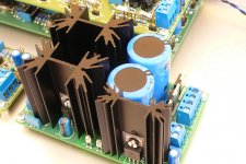 094 Method of Assembly - PSU PCB.JPG679.1 KB · Views: 222
 -
 097 Method of Assembly - PSU PCB From Above.JPG576.2 KB · Views: 203
Mechanical Assembly 5
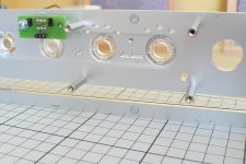
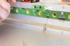
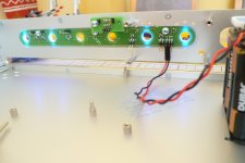
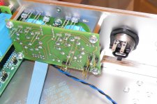
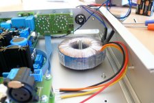
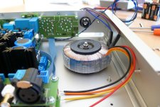
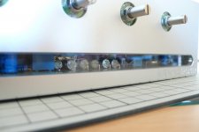
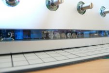
In these photos, you can see how the re-designed rotary switch PCB fits. The LEDs will be pushed into the front panel so that they are flush with the outer surface and then I will solder them inplace. You can also just make out the LLLL LED, also flush with the front panel. My re-designed PCB realigns the rotary switches - Elektor's original board made no sense! Also I have added the 2mm blue LEDs to show the selection made. The LLLL LED is a 5mm flat-top type.
My wife is the photographer - she captured the last 3 photos really well considering she moved while I assembled the transformer Run them in sequence and you can see the building in progress!
Stay tuned for the top panel...
In these photos, you can see how the re-designed rotary switch PCB fits. The LEDs will be pushed into the front panel so that they are flush with the outer surface and then I will solder them inplace. You can also just make out the LLLL LED, also flush with the front panel. My re-designed PCB realigns the rotary switches - Elektor's original board made no sense! Also I have added the 2mm blue LEDs to show the selection made. The LLLL LED is a 5mm flat-top type.
My wife is the photographer - she captured the last 3 photos really well considering she moved while I assembled the transformer
Run them in sequence and you can see the building in progress! Stay tuned for the top panel...
Attachments
-
 098 Method of Assembly - Fitting the Rotary Switch PCB.JPG678 KB · Views: 220
 -
 101 Method of Assembly - Selector Switches.JPG634.3 KB · Views: 211
 -
 102 Method of Assembly - Power Switch.JPG675.7 KB · Views: 189
 -
 103 Method of Assembly - Power Switch Fitted.JPG640 KB · Views: 162
 -
 104 Method of Assembly - Rear of Front Panel.JPG753.1 KB · Views: 194
 -
 109 Method of Assembly - Fitting Left Channel Input PCB.JPG596.5 KB · Views: 248
 -
 112 Method of Assembly - Transformer Mounting.JPG694.1 KB · Views: 213
 -
 113 Method of Assembly - Transformer.JPG577.3 KB · Views: 165
 -
 114 Method of Assembly - Transformer Complete.JPG596.2 KB · Views: 210
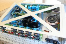
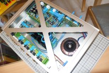
Mechanical Assembly 6 - The last one!
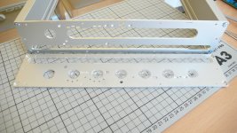
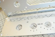
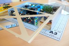
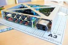
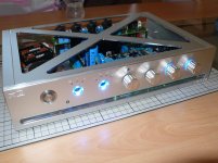
Here you can see the top panel. It has the same tongue and slot fixings as the side and bottom panels. It will eventually have perspex in the triangles. This panel was one of the most complicated to do in Front Panel Designer. The first version had slots for the triangular cutouts, but I found that if you insert a rectangular hole and set it to triangle, you can save money! The perspex panel to go under it will have to have curved slots to match the radii of the triangles' corners. I will take photos of this when I finish designing it and it arrives.
Next up, some overview pics...
Here you can see the top panel. It has the same tongue and slot fixings as the side and bottom panels. It will eventually have perspex in the triangles. This panel was one of the most complicated to do in Front Panel Designer. The first version had slots for the triangular cutouts, but I found that if you insert a rectangular hole and set it to triangle, you can save money
! The perspex panel to go under it will have to have curved slots to match the radii of the triangles' corners. I will take photos of this when I finish designing it and it arrives.Next up, some overview pics...
Attachments
General Photos...
Just some general photos...
Now I have to remove the lid, wire-up, design the rear panel and top perspex panel and it will be completed! Whew!
I'm also building the Op-Amplifier for the same project. Watch out for those photos in the chip amp section soon...
Bye for now,
Dave.
Just some general photos...
Now I have to remove the lid, wire-up, design the rear panel and top perspex panel and it will be completed! Whew!
I'm also building the Op-Amplifier for the same project. Watch out for those photos in the chip amp section soon...
Bye for now,
Dave.
Attachments
-
 122 Front View.JPG573 KB · Views: 214
 -
 124 Right Side.JPG605.6 KB · Views: 141
 -
 125 View Through Slot.JPG530.6 KB · Views: 135
 -
 126 View Through Slot.JPG589.7 KB · Views: 113
 -
 127 View Through Slot.JPG598.5 KB · Views: 100
 -
 128 Power Switch and LLLL Control.JPG586.8 KB · Views: 122
 -
 129 Front Left.JPG610.8 KB · Views: 146
 -
 131 Blue Lights.JPG724.3 KB · Views: 194
 -
 132 Knobs On!.JPG815.7 KB · Views: 215
 -
 138 Overview with Blue LEDs Lit.jpg202.9 KB · Views: 236
Where can i get documentation and Bom for this Pre-Amp?, It seems like a very worthwhile and ambitious project.
The original project was covered in Elektor Magazine in the April - June 2012 issues. I have changed quite a few components from those used by Elektor due to my blue theme. I also re-designed the rotary switch PCB and designed separate PCBs for the Tone Defeat switch and the MM/MC and IEC Amendment switches. The illumination PCB is also my own design. All the aluminium panels were also designed by me using Front Panel Designer and manufactured by Schaeffer of Germany.
I am working on a parts list with prices (current at the time of writing), but this is not at the top of my priorities right now
Cheers,
Dave.
- Status
- This old topic is closed. If you want to reopen this topic, contact a moderator using the "Report Post" button.
- Home
- Source & Line
- Analog Line Level
- Douglas Self PreAmp 2012