Yes I have searched the internet. I have not searched here, because I suspect I will get 5 bazillion hits (it is so basic). However, whenever I search for "series HPF" or similar, I just never get what I am looking for. So, here it is...
I understand how a basic LPF/HPF works, like so:

The capacitor interacts with the resistor to pass certain frequencies to ground, allowing the remaining frequencies to pass through untouched. So, if we follow that logic, shouldn't the reverse order of components, but in series with no ground, be the same filter (although to a much lesser degree). Here is a graphic to illustrate what I mean.

I say reversed because a typical LPF would be resister first, then cap to ground. In series, wouldn't it be cap then resistor then signal out (no ground)?
That way, if I see such a setup in a feedback loop, headed to ground, then it sends those matching frequencies to ground, amplifying the rest of the signal? Such as a capacitor to a resistor to ground (sending lows to ground), would amplify highs?
I understand how a basic LPF/HPF works, like so:
The capacitor interacts with the resistor to pass certain frequencies to ground, allowing the remaining frequencies to pass through untouched. So, if we follow that logic, shouldn't the reverse order of components, but in series with no ground, be the same filter (although to a much lesser degree). Here is a graphic to illustrate what I mean.
I say reversed because a typical LPF would be resister first, then cap to ground. In series, wouldn't it be cap then resistor then signal out (no ground)?
That way, if I see such a setup in a feedback loop, headed to ground, then it sends those matching frequencies to ground, amplifying the rest of the signal? Such as a capacitor to a resistor to ground (sending lows to ground), would amplify highs?
None are so blind as those who use the wrong search terms. ;-)Yes I have searched the internet. ....
That way, if I see such a setup in a feedback loop, headed to ground, then it sends those matching frequencies to ground, amplifying the rest of the signal? Such as a capacitor to a resistor to ground (sending lows to ground), would amplify highs?
Start here. Search terms: Nyquist, Bode, feedback, filtering, Laplace
Then find any first year analog electronics text. Followed by The Art of Electronics (nice arguement about it here)
So, if we follow that logic, shouldn't the reverse order of components, but in series with no ground, be the same filter (although to a much lesser degree). Here is a graphic to illustrate what I mean.
View attachment 401699
I say reversed because a typical LPF would be resister first, then cap to ground. In series, wouldn't it be cap then resistor then signal out (no ground)?
That way, if I see such a setup in a feedback loop, headed to ground, then it sends those matching frequencies to ground, amplifying the rest of the signal? Such as a capacitor to a resistor to ground (sending lows to ground), would amplify highs?
Lets put this in an easy to understand nutshell and then you can work it out with real numbers.
To make things easy lets think in terms of ohms law. The "resistance" of the cap at any given frequency is R= 1 divided by (2pi*f*c).
So pick any value of cap you want and any frequency. Lets be silly and say 10 pico farads and 100Hz. The cap has a "resistance" of 160 meg ohms at 100Hz.
Put that value into your lower diagram. Now pick any value for the series resistor. You have the same AC voltage at the output as at the input for both your two last examples.
Can you see why ? How might you actually measure it though and what effect would you see with a typical scope of DVM ?
Ah, okay, without looking up any of the resources you mentioned (thanks), and without performing any tests (lacking signal generator - gonna have to build one), it looks like the standard LPF/HPF would be forming a frequency dependant voltage divider.
So, therefore, if they were in series, they would be a frequency dependant resistor - not to mention blocking DC. It would present more resistance at lower frequencies, and would not matter what order you placed them in. It would be a high pass filter either way.
So after thinking this way... I see now that usually when I see this, it is actually in a divided negative feedback loop of an opamp, and is actually part of the out-bound half of a voltage divider. This causes the lower frequencies to hit more resistance, which in turn causes the opamp to attenuate low freqs relative to high. I would like to see it as the highs are "led away", so the opamp has to push them harder to get everything "even", which in the end, boosts the highs more than the lows (when higher than unity). Or attenuate the highs less than the lows if gain < 1. But I don't know if that is actually "terminoligically" correct.
I wasn't looking at the whole picture.
So, what about an audio amp snubber circuit on the output of a chipamp? Seems that would be sending highs (way highs) to ground, and therefore a basic low pass filter. I could see that being needed to help stabilize. I could also see this "frequency dependant resister" resisting varying levels of current depending the frequency (a frequency dependant power resistor?). I remember seeing something about them "preventing potential oscillation due to inductive loading" and being for "high frequency stabilization".
So if I were to need to substitute parts in a snubber circuit, could I calculate the corner frequency of the snubber, then use the parts I have to reproduce the same frequency?
For example, the circuit/schematic calls for 1ohm and 0.22uF. The corner comes out around 725k. I do not have any 1 ohm, but I do have 5. To get the same corner I would need 0.044 uF (instead of 0.22). Can I treat this snubber circuit this way?
Erm, I think I found the answer to that. To quote from http://www.diyaudio.com/forums/chip-amps/120028-boucherot-cell-zobel-network-values.html (reply # 7)
This output RC does several things:
1) together with the open-loop Rout of the amplifier it forms a pole and a zero in the open-loop gain, which, if choosen properly, reduce risk of feedback loop instability with capacitive load. Wrong values increase instability, though.
2) it compensates/damps oscillation tendencies of capacitively loaded emitter followers.
3) with quasi-comp. outputs (the bottom of the LM3886 etc is a NPN-Power transistor in a CFP hookup) it damps the tendency of oscillation of the CFP output.
2) and 3) are the more important parasitic effects, 1) is a control loop theory thing which is more or less insignificant when the snubber R >> Rout (that is, the pole and the zero are too close), which is quite often the case. Therefore the best values are normally found empirically.
4) It can be "misused" to linearize/flatten the speaker impedance at HF. This should better be done after a series L//R and right at the speaker (where it could be dimensioned to approach cable HF impedance to terminate it, which is of importance with high bandwidth amp -- not chip-amp territory, typically)
The cap isolates DC/LF current and is normally chosen to kick in just above the audio range (but still it must be capacitive at HF, which is actually more important), while the resistor is the part that "does the work", and it must be a low inductance type and also wired with low inductance, btw preferably directly to the neg. supply (which must be bypassed also directly to the pos. supply, or alternatively split up the snubber cap in a center tapped cap between the supplies).
So I take it that substituting parts in a snubber is not that easy. Now to try and find formulas for that...1) together with the open-loop Rout of the amplifier it forms a pole and a zero in the open-loop gain, which, if choosen properly, reduce risk of feedback loop instability with capacitive load. Wrong values increase instability, though.
2) it compensates/damps oscillation tendencies of capacitively loaded emitter followers.
3) with quasi-comp. outputs (the bottom of the LM3886 etc is a NPN-Power transistor in a CFP hookup) it damps the tendency of oscillation of the CFP output.
2) and 3) are the more important parasitic effects, 1) is a control loop theory thing which is more or less insignificant when the snubber R >> Rout (that is, the pole and the zero are too close), which is quite often the case. Therefore the best values are normally found empirically.
4) It can be "misused" to linearize/flatten the speaker impedance at HF. This should better be done after a series L//R and right at the speaker (where it could be dimensioned to approach cable HF impedance to terminate it, which is of importance with high bandwidth amp -- not chip-amp territory, typically)
The cap isolates DC/LF current and is normally chosen to kick in just above the audio range (but still it must be capacitive at HF, which is actually more important), while the resistor is the part that "does the work", and it must be a low inductance type and also wired with low inductance, btw preferably directly to the neg. supply (which must be bypassed also directly to the pos. supply, or alternatively split up the snubber cap in a center tapped cap between the supplies).
Last edited:
Ah, okay, without looking up any of the resources you mentioned (thanks), and without performing any tests (lacking signal generator - gonna have to build one), it looks like the standard LPF/HPF would be forming a frequency dependant voltage divider.
So, therefore, if they were in series, they would be a frequency dependant resistor - not to mention blocking DC. It would present more resistance at lower frequencies, and would not matter what order you placed them in. It would be a high pass filter either way.
So after thinking this way... I see now that usually when I see this, it is actually in a divided negative feedback loop of an opamp, and is actually part of the out-bound half of a voltage divider. This causes the lower frequencies to hit more resistance, which in turn causes the opamp to attenuate low freqs relative to high. I would like to see it as the highs are "led away", so the opamp has to push them harder to get everything "even", which in the end, boosts the highs more than the lows (when higher than unity). Or attenuate the highs less than the lows if gain < 1. But I don't know if that is actually "terminoligically" correct.
I wasn't looking at the whole picture.
So, what about an audio amp snubber circuit on the output of a chipamp? Seems that would be sending highs (way highs) to ground, and therefore a basic low pass filter. I could see that being needed to help stabilize. I could also see this "frequency dependant resister" resisting varying levels of current depending the frequency (a frequency dependant power resistor?). I remember seeing something about them "preventing potential oscillation due to inductive loading" and being for "high frequency stabilization".
So if I were to need to substitute parts in a snubber circuit, could I calculate the corner frequency of the snubber, then use the parts I have to reproduce the same frequency?
For example, the circuit/schematic calls for 1ohm and 0.22uF. The corner comes out around 725k. I do not have any 1 ohm, but I do have 5. To get the same corner I would need 0.044 uF (instead of 0.22). Can I treat this snubber circuit this way?
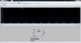
Why don't you try simulating your circuits and ideas. It would help you understand what happens better.
Here is your filter circuit shown in "Example 1". The green and blue traces are identical and overlaid. The output and input are identical because there is no return current and the measuring device "ideal". It draws no current during testing.
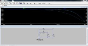
Example 2 shows the response of your two different networks. I've made the cap 0.047 rather than 0.044 so that a slight difference occurs and you can see the two traces. You can see the -3db point is where you calculated.
Attachments
That way, if I see such a setup in a feedback loop, headed to ground, then it sends those matching frequencies to ground, amplifying the rest of the signal? Such as a capacitor to a resistor to ground (sending lows to ground), would amplify highs?
I suspect that part of your confusion is because your circuit diagrams make it appear as though the resistor is a frequency dependent element, steering high frequency current to the next stage while steering low frequency current to ground. Of course, a resistor treats both high and low frequency currents the same. Only the capacitor is a frequency dependent impedance. Because any passive filter must be comprised of at least two impedance terms, where at least one of those terms is frequency dependent, the resistor's only function here is to provide a non-frequency dependent impedance term. The capacitor then provides the frequency dependent impedance needed to create a filter.
@Mooly - Thanks, its clear I'm going to have to learn to use some circuit analysis software. I've got several programs, but have not dedicated the time to actually learning fully how to use them.
@Ken - Yes, I've been treating the cap/resistor pair as a unit. I see now that in the divided negative feedback loop, the resister is acting as the gain portion and the cap is attenuating the highs.
So in the snubber, the resistor is doing the impedance matching (for the load) and the cap is the filter?
But I think playing with Spice for a couple of months (heh) may clear up my understanding of some of these principles. Up until now, I've been merely copying some of this stuff from other circuits without fully understanding what it is doing. And then experimenting (swapping out parts) and listening to what is happening, very likely not getting the best solutions.
- Status
- This old topic is closed. If you want to reopen this topic, contact a moderator using the "Report Post" button.
- Home
- Source & Line
- Analog Line Level
- Please confirm something basic for me