You are missing the point that Calvin and myself are making. We both understand the circuit, but you are reading differently what we are writing.
Put 13.5k from U2 output to inverting input.
Hi Richie00boy,
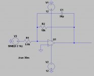
I am sorry if I was misunderstood both of you. So do you actually mean the feedback loop below doesn't work?
Adding 13.5k just can't realize the fully differential output capability. When only SE signal is provided, one output is larger than the other.
Attachments
I wish people would learn to draw schematics in some sort of rational conventional way ")
I realise that the original schema in this thread is how one can fling it together to stuff it into a sim, but my old-fashioned brain finds it too confusing.
I have simplified it to MY tastes and experience. Sorry I have nothing but a pen to hand.
It seems to me that this circuit is very problematic.
There are two feedback paths for U2 - via U1 and U3 in parallel. I do not see how stability can be achieved. Because U2 is open loop (locally), its o/p will .... do what?
I it is not clear to me what is being attempted here!
Attachments
same
No it's not. The circuit we have been discussing has 3 op-amps. That has two.
No it's not. The circuit we have been discussing has 3 op-amps. That has two.
Trace the signal in and the feedback path.
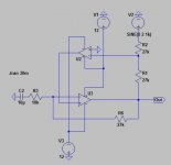
Finally I managed to stop the opamp from ocsillation by adding C3 to compensate the circuit. The SAW wave oscillation is gone completely. Zoomed in the scope to 2mV/div and only can read some "dirty noise" that is less than 1mV.

Both output is giving same output voltage amplitude when SE source/ Balanced source is used. So this is what I wanted in the earlier time, a fully differential design.
Attachments
Last edited:
I wish people would learn to draw schematics in some sort of rational conventional way
I realise that the original schema in this thread is how one can fling it together to stuff it into a sim, but my old-fashioned brain finds it too confusing.
I have simplified it to MY tastes and experience. Sorry I have nothing but a pen to hand.
It seems to me that this circuit is very problematic.
There are two feedback paths for U2 - via U1 and U3 in parallel. I do not see how stability can be achieved. Because U2 is open loop (locally), its o/p will .... do what?
I it is not clear to me what is being attempted here!
Ya, I am still learning to draw it nicely in the software, but sometimes I am too lazy for that

At very first, this circuit looks problematic on my eyes too, 'dual active unity gain feedback' loop( I don't know how to call it). But after look into the circuit, well it just worth to give it a try, and I managed to make it stable and works now
Performance wise, I have yet to measure it.
Trace the signal in and the feedback path.
Yes, and yet again you totally miss the point I have been making. The circuits are not the same
Finally I managed to stop the opamp from ocsillation by adding C3 to compensate the circuit.
Glad you have a fix. What a surprise it is in essence very similar to what we were telling you to do...
Yes, and yet again you totally miss the point I have been making. The circuits are not the same
Glad you have a fix. What a surprise it is in essence very similar to what we were telling you to do...
Oh is it?
another point shown wrong in the earlier pics: using tihs type of full diff circuit requires both + and - inputs to be tied to low, matching Z source - can't leave one floating for single ended
in fact it would behave poorly with most single ended audio sources which have series R in the signal lead
you need to buffer both inputs for a truely general purpose circuit
in fact it would behave poorly with most single ended audio sources which have series R in the signal lead
you need to buffer both inputs for a truely general purpose circuit
another point shown wrong in the earlier pics: using tihs type of full diff circuit requires both + and - inputs to be tied to low, matching Z source - can't leave one floating for single ended
in fact it would behave poorly with most single ended audio sources which have series R in the signal lead
you need to buffer both inputs for a truely general purpose circuit
Thanks JCX, will look into this problem and try to come back with a better schematic.
Hi,
is it?
Yes it is! Adding the cap is nothing else but giving U2 its own feedback loop.
I´m a bit surprised only by the fact that the cap seems sufficient here, as I´d expected that a resistor would have been needed too to get U2´s gain down.
I admit, that I didn´t analyze the circuit as thorough as needed regarding the function of U2 not only supplying for a DC-Bias, but also to feed the input signal of one input to the second input to achieve balanced output under all circumstances.
The doubt about U2 running openloop beeing the source of oscillation seems to be correct, eyh?
jauu
Calvin
Hi,
is it?
Yes it is! Adding the cap is nothing else but giving U2 its own feedback loop.
I´m a bit surprised only by the fact that the cap seems sufficient here, as I´d expected that a resistor would have been needed too to get U2´s gain down.
I admit, that I didn´t analyze the circuit as thorough as needed regarding the function of U2 not only supplying for a DC-Bias, but also to feed the input signal of one input to the second input to achieve balanced output under all circumstances.
The doubt about U2 running openloop beeing the source of oscillation seems to be correct, eyh?
jauu
Calvin
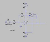
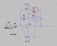
Is U1 running in complete Open loop?
*JPG1
I am using a very ordinary way to compensate the opamp, connecting a resistor from the output back to the inverting input to reduce or increase the gain is just a complete different story.
*JPG2
Back to the very basic circuit to compensate an oscillated basic opamp. Now you can illustrate what I was actually doing that.
*JPG3
Attachments
Last edited:
Hi,
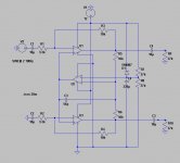
I now hacked the circuit from #1 into the sim.
Using OPA134 Model the sim showed oscillation ~6.5MHz.
A increase of the feedback caps C6 and C7 from 12p to 27p and adding a local feedback cap of just 4p7 to U2 cleaned up things.
Simming with a 10kHz rectangle the tiny cap cleaned up U2s response.
Larger Caps for U2 worsened the Step response of the whole circuit, looking like typical slewrate induced distortion.
jauu
Calvin
Attachments
- Status
- This old topic is closed. If you want to reopen this topic, contact a moderator using the "Report Post" button.
- Home
- Source & Line
- Analog Line Level
- Opamp Having Oscillation