So I've got some Yamaha MSP7 active monitors and they have been all around great speakers for home studio use in a semi DIY "treated" room.
I have to admit however that I'm a little curious about how upgrades may bring them further into their element.
That is, I'm thinking about swapping out the ghastly 4558's for newer op amps with better noise, distortion and DC specs.
In the attached schematic you'll see that every 4558 has a 22pF cap across its inputs.
My question is - what is the purpose of this cap?
I read up on Lead-Lag Compensation and in my foggy lay understanding I think the 22pF serves to limit high frequency response - for stability's sake as well as to protect against RF interference?
I'm wondering, with the 4558's already relatively low bandwidth (3Mhz) and the copious filtering going on around them in the feedback loops (see schematic attached), how necessary is this 22pF cap?
Without removing it, would it render changing the op amps pointless?
Attachments
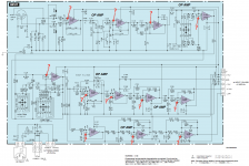
I'd guess someone did some copy & paste there. These caps are typically found in phono stages (with values in the hundreds of pF) so should aid EMI rejection in low-level stages (like IC101), but they are definitely not necessary everywhere. You can see them as a high-frequency bootstrap or GBW drain. If you feel like it, you could try removing one at a time and checking cellphone sensitivity.
In terms of opamps, yes, those 4558s are a little long in the tooth. They should nonetheless do an OK job as a "one size fits all" type here. IC101 could use something with a little lower noise, while the filter stages appreciate something with low input impedance distortion and moderate current noise. LM4562s should actually work quite well everywhere. With the better output drive capabilities of the modern type, you could also cut R177/178 values by about a factor of 2 for even lower noise, though you should determine where the volume pot is typically set at in order not to throw off impedance balance (inverting vs. noninverting) too much.
In terms of opamps, yes, those 4558s are a little long in the tooth. They should nonetheless do an OK job as a "one size fits all" type here. IC101 could use something with a little lower noise, while the filter stages appreciate something with low input impedance distortion and moderate current noise. LM4562s should actually work quite well everywhere. With the better output drive capabilities of the modern type, you could also cut R177/178 values by about a factor of 2 for even lower noise, though you should determine where the volume pot is typically set at in order not to throw off impedance balance (inverting vs. noninverting) too much.
LM4562s should actually work quite well everywhere. With the better output drive capabilities of the modern type, you could also cut R177/178 values by about a factor of 2 for even lower noise, though you should determine where the volume pot is typically set at in order not to throw off impedance balance (inverting vs. noninverting) too much.
Thanks, I guess you're speaking about the resistances seen by the + / - input bias currents?
I was thinking about using OPA1612, partly because I have a couple on hand.
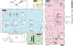
Another thing I think is cheesy about this design is that apparently even if the filters are set to "flat", the signal has no choice but to pass through the multiple op amp stages (block diagram attached).
I never use the filters anyway.
Attachments
Without removing it, would it render changing the op amps pointless?
Yes - with faster opamps it may even lead to oscillation.
Also rather pointless improving the opamps without changing the grounding. The decoupling caps as shown pump noise into signal ground from the rails. Noise is created on power rails by opamps' classB output stage.
Noise is created on power rails by opamps' classB output stage.
You mean from the supply current transients feeding the push-pull stages - under the influence of power rail inductance?
Couldn't cleaner supplies with lower output impedance be of some benefit here?
Yes and yes. Not just power rail inductance, resistance too. Most of the time I look at commercial opamp-based circuits, the supply rail impedance I see isn't particularly low. Decoupling caps are generally hugely undersized for high quality audio reproduction.
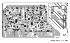
So then it makes me wonder if adding parallel/beefier wiring for the supply rails is in order.
As you can see in the attached pic there are some jumpers distributing the rails around the board.
Attachments
@CZ101 Did you ever make any mods? My MSP7s have been noisy since day 1. Pretty disappointing actually for what is a decent monitor. Would really love someone with the goods to provide some specific direction on improving these amps.
Not yet. But if I were to try something today, I would experiment with placing an op amp like the OPA2227 in the input stage, whose GBW is similar to the 4558 but with much better noise, distortion and DC specs.
Once a better op amp is in place, probably some of the coupling caps could be removed.
On that note, if you don't use the "Room EQ" correction filters, look into just bypassing that crap with a wire to the crossover stage op amp, which also should be replaced with something better.
I would also want to check how closely matched the resistors are at the input stage. Tightening up the matching could improve CMR.
"The addition of input, output, or load capacitance to an op
amp circuit decreases stability, which leads to overshoot in
the time domain. The stability decrease is worse for a
buffer than for other amplifier configurations."
http://notes-application.abcelectronique.com/001/1-112.pdf
amp circuit decreases stability, which leads to overshoot in
the time domain. The stability decrease is worse for a
buffer than for other amplifier configurations."
http://notes-application.abcelectronique.com/001/1-112.pdf
I think I know why they may have put the cap across the inputs.
These are filter stages and buffers.
Some opamps are unity gain stable, but can show problems when the gain is <<1. The 22 pF raises the noise gain at HF, providing a bit more gain margin.
Do you know of any online literature about this (or in print)? I need to read more about it.
Having a gain <<1 would seem to only apply in the inverting case. Is this what you're referring to - the inverting filter stages?
Do you know of any online literature about this (or in print)? I need to read more about it.
Having a gain <<1 would seem to only apply in the inverting case. Is this what you're referring to - the inverting filter stages?
You can reduce the noise gain of non inverting stages and buffers too, and in just the same way as long as there is a resistance added between the opamp output and the inverting input.
Here is the technique in practice although this was applied resistively and so the reduction in loop gain occurs all the way down to DC.
http://www.diyaudio.com/forums/analog-line-level/196461-different-opamp-compensation-technique.html
Attachments
- Status
- This old topic is closed. If you want to reopen this topic, contact a moderator using the "Report Post" button.
- Home
- Source & Line
- Analog Line Level
- Yamaha MSP7 − 22pF between Op Amp inputs? Why?