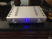
I finally put together my second Kuartlotron superbuffer. I had some builder issue on the first buffer that finally got resolved. I triple checked everything on this build before soldering parts in. I did sell the first buffer, but regretted it and had to build this one.
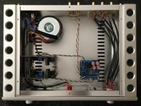
This build used the second version of the PCBs which have the shuntregs. I did not use the on the onboard shuntregs, but instead used two of RJM's S-regs, one for each channel. It was probably over kill, but that's okay. The S-regs are nice boards that fit the bill for this build. I also used a 50K eBay DACT and a 3 position 4 pole Grayhill switch.
The final result is a very nice sounding preamp with great imaging that works very well with my Folsom amp.
Attachments
Hi, I have a question about switch type and contact material.
I want to build a Kuartlotron with a selector switch in it. 2 in 1 out, what switch, toggle or rotary and what should the contact be, gold, silver or ???.
Thanks in advance, more questions to follow.
Alan.
I want to build a Kuartlotron with a selector switch in it. 2 in 1 out, what switch, toggle or rotary and what should the contact be, gold, silver or ???.
Thanks in advance, more questions to follow.
Alan.
Last edited:
Hi all, I'm planning to buy some lifepo4 batteries for my newly bought Kuartlotron. Any opinion on whether I should go for slightly above the recommended dual 10V, or below? Since they will drift we're maybe talking up to 1V above or below. Thanks for any input
I would say go slightly above.
Hi, I have a question about switch type and contact material.
I want to build a Kuartlotron with a selector switch in it. 2 in 1 out, what switch, toggle or rotary and what should the contact be, gold, silver or ???.
Thanks in advance, more questions to follow.
Alan.
I suggest a 3-pole switch so you can switch ground along with R and L, therefore keeping the source grounds separate. Other than that, I have no experience with what switches work best. However I think any switch that is not known for problems will get you 99% of the way there.
Thanks Kean, would you say the Kuartlotron is sensitive to variations in voltage? Is 9V significantly worse than 10V or is it barely detectable? Sorry if repeating myselfI would say go slightly above.

Asking as I've been a bit deluded by battery sellers; with lifepo4 only 9.6V nominal (should be possible to keep between 9.9 fully charged and 9.3) or 12.8V is possible
Keantoken said some people thought high voltage didn't sound as good. I forget what mine is at but it's well above 10v, and there are zero issues with it.
I personally doubt you can tell the difference. If you understand how the circuit works to some degree you start to see how the DC voltage really just needs to be enough to divide into 4ish and be at the vrms output of the source; and how the input and output of the signal doesn't really care what the DC voltage is at all. The claim is sonic attributes, not function, with increasing voltage.
I'd go with a 12/12.8v battery personally. Batteries often insta-sag to a little less voltage if they are not rather big compared to the current demand, and I wouldn't want to have my buffer clipping after playing for a short time if I had a hot source.
Thanks a lot both. I think I will go for the flexible solution with single batteries + bms'es instead of finished packages, that way I can change the voltage by adding/removing a battery if I want. Probably something like 6pcs of 32650, should be dimensioned on the very generous side and provide power for hundreds of hours without the regulators. Will let know how it goes. Destroyer are you saying that the voltage/4 just needs to be above the source's output? My output is 2.1Vrms, so I hope it'll be fine9.3-9.9 is close enough to 10V, I would just use that and take advantage of the longer battery life.
Last edited:
Absolutely loving the Kuartlotron. However my amp already has DC blocking caps, so I guess I could short the output capacitors in the K. But - which ones are that again?;-)
An externally hosted image should be here but it was not working when we last tested it.
Absolutely loving the Kuartlotron. However my amp already has DC blocking caps, so I guess I could short the output capacitors in the K. But - which ones are that again?;-)
An externally hosted image should be here but it was not working when we last tested it.
there are no DC blocking caps in this buffer
there are no DC blocking caps in this buffer
Thanks Ricardo, I must have misunderstood a post in the thread at some point. But guess it was a good decision to ask before I shorted them then
Some of you may have noticed that the transistors in the Mouser BOM have changed to OnSemi. This is because Fairchild was acquired by OnSemi and the Fairchild listings were renamed to OnSemi. It is highly probable they are still the Fairchild parts, just under new branding.
If anyone has trouble, let me know.
If anyone has trouble, let me know.
Hi
I just finished assemble a pair of boards and now im setting the trimpots according to instruction. First step I managed to get 5v at TP by adjusting R5. But I have trouble on the second step. I cant get a steady 0V on the input. What i mean by steady is when adjust the dc trim i can make it 0V but after that it will go down to -0.1, -0.2, -0.3 and so on until -2.1mV where i gave up waiting for it. Output offset is about 10mV.
I can get 0V on output but on the input it will be wayoff from 0V. Could someone please tell me what i have done wrong?
All parts are according to BOM, soldering joints are ok, caps polarity is also ok. Powered them with a small smps with an output +11.94v and -12.15v.
Power supply questions
So I don't understand much of the electronics, but I can read reviews that the Kuartlotron is good and I can solder so I bought some boards. But I have a few questions about powering it...
1) I am going to order the parts off Mouser. I can choose whatever input voltage is recommended, so I don't need the other resistors. Is there a recommended input voltage?
2) I am going to build an Elliot Sound Products Project 06 Phono Preamp and Project 05C preamp power supply. I see some posts on the potentiometer going before the buffer, so would it go Turntable-->Phono Preamp-->Pot-->Kuartlotron-->Amplifier?
3) The Project 05C power supply is adjustable between +/- 2.5V to +/- 25V. Can I just use this power supply configured to the recommendation to question (1) above, or is it more complicated than that?
Thanks for any help.
Kuartlotron R2 PCB info:
2: The resistors marked with an asterisk on the PCB need to be determined based on your input voltage. Included in the Mouser cart are resistors for a range of input voltages:
12V - 68R
13V - 120R
14V-15V - 150R
15V-16V - 196R 1/2W
17V-19V - 332R 1/2W
You can delete from the cart the resistors you don't need.
So I don't understand much of the electronics, but I can read reviews that the Kuartlotron is good and I can solder so I bought some boards. But I have a few questions about powering it...
1) I am going to order the parts off Mouser. I can choose whatever input voltage is recommended, so I don't need the other resistors. Is there a recommended input voltage?
2) I am going to build an Elliot Sound Products Project 06 Phono Preamp and Project 05C preamp power supply. I see some posts on the potentiometer going before the buffer, so would it go Turntable-->Phono Preamp-->Pot-->Kuartlotron-->Amplifier?
3) The Project 05C power supply is adjustable between +/- 2.5V to +/- 25V. Can I just use this power supply configured to the recommendation to question (1) above, or is it more complicated than that?
Thanks for any help.
- Home
- Source & Line
- Analog Line Level
- The Kuartlotron - keantoken's simple error-correction superbuffer