Hi ")
With "little" delay I tried Germanium version of this buffer.
And it was OMG sound last evening...
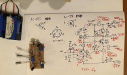
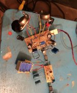
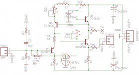
Circuit working with Ge devices AC187 and AC188.
For the test I not solder unmark parts, RC input filter, choke 2.2uH.
Capacitors at the PS are ommited too because I power device from the 2x9V battery pack.
Rest 2 capacitors was 10uF (against 470uF in the original sch.)
.
-It was possibile to set 1/2 +V at the test point.
-I just set another pot to 56ohms didnt measure and eventualy correct dist yet.
-off set is about -40mV with (I think) pot of 2M full value. Initialy was -52mV and with inreasig value droped.
-Transistors randomly picked.
-No overheating, 1st pair are consume about 4mA second pair is about 8.5mA.
-Second pair just slightly warm. First pair are cold.
-Circuit not showing any hum or his. Very silent.
I tried with Quad II power amplifier and with transformer input Western Electric Germanium amplifier.
.
The sound was vey good. Natural and with "body". Digital media are somehow moved to analog sound and made ballans with start-finish of the tone. Not to emhesize the finishing HF end. Circuit with Ge somehow "reduce" digital "signature". Instruments are neutral and transpraent, echoes are clear and also with fundament. Bass is very good.
But the voices are beautiful
.
I just listen one channel last evening until I the batteries are almost drained
With "little" delay I tried Germanium version of this buffer.
And it was OMG sound last evening...
Circuit working with Ge devices AC187 and AC188.
For the test I not solder unmark parts, RC input filter, choke 2.2uH.
Capacitors at the PS are ommited too because I power device from the 2x9V battery pack.
Rest 2 capacitors was 10uF (against 470uF in the original sch.)
.
-It was possibile to set 1/2 +V at the test point.
-I just set another pot to 56ohms didnt measure and eventualy correct dist yet.
-off set is about -40mV with (I think) pot of 2M full value. Initialy was -52mV and with inreasig value droped.
-Transistors randomly picked.
-No overheating, 1st pair are consume about 4mA second pair is about 8.5mA.
-Second pair just slightly warm. First pair are cold.
-Circuit not showing any hum or his. Very silent.
I tried with Quad II power amplifier and with transformer input Western Electric Germanium amplifier.
.
The sound was vey good. Natural and with "body". Digital media are somehow moved to analog sound and made ballans with start-finish of the tone. Not to emhesize the finishing HF end. Circuit with Ge somehow "reduce" digital "signature". Instruments are neutral and transpraent, echoes are clear and also with fundament. Bass is very good.
But the voices are beautiful
.
I just listen one channel last evening until I the batteries are almost drained
Attachments
I didnt measure
was involved to listen as much as batteries hold
one channel only
I just set the 100ohm trimmer to 56ohm value lsame ike fixed resistor (not measured, I should...) and not touch that part.
But I measure total distortion with buffer in system (experimantal dac-filter-buffer and it was delta only in 0.01-0.015 to naked dac output. That is with passive 5ord filter and 10K@input buffer. That is not huge but dac module have 2.5K of output Req. So this 10K input res. probably "damped" more than it should.
.
The transfer is pretty flat even with 10uF of C inside the circuit used against 470uF. (i didnt have when soldering...). No any cut of low end
.
I MUST prepare one IV converter circuit from Ge transistors, after even small listeninig of this Ge version buffer...
.
I have some Q about the using Ge:
- What is higher value of Rin that could be used?
- Can I use higher supply voltage?
- Is that currents of 4mA(input branch) and 8.5mA good?
- Can I use other types for output NPN stage, like AD161?
- Can I ommit output serial reistor (when loading output with transformer)
.
cheer and thanks
Last edited:
Yes, thermal coupling doesn't matter much here because the tranistors all heat up equally. Where it might be useful is if the board is mounted with a hot heatsink on one side.
The specified transistors have fairly consistent Vbe, but some of your offset could be coming from your Ge transistors. You would measure this by measuring the voltage between input and output. If so you might be able to reduce it by swapping the PNP or NPN transistors.
If you can reduce offset to zero with the trimmer, then what's left is thermal drift. At some point as you increase source resistance (including the input resistor) the thermal drift will become tunmanageable. I don't know what that would be for Ge transistors and I hear the AC127/128 can be highly variable between batches and manufacturer. But if it will be permanently used with your DAC with 2.5k output resistance, you could actually remove the input resistor as it is only there in case the source is disconnected.
4mA and 8mA are fine and might actually be better for Ge transistors if the input transistor is slow. On the other hand by reducing the input transistor bias you may reduce distortion by reducing the harmonic currents from the input transistor base. You can do this by changing the 56R resistors.
Last edited:
Thanks for useful informations.
Can I rise a bit power supply voltages?
To say +-12V or +-15V?
Then transistors will opperate at 6 or 7.5V supply individualy?
I supose that currents will be higher but not sugnificantly if I rise proportionally 1K R from -V and 1K R from +V?
Now transistors are cca about 4-4.3V from B to C...
.
What maximum signal P-P the buffer can transfer without clipping?
.
Will be some benefits to use JFET Isource insted 3.6K R?
.
I am far from "expert" in transistors field, please explain more about
"If so you might be able to reduce it by swapping the PNP or NPN transistors."
or make some sketch?
.
cheers.
Last edited:
Ahaa.
I see now. I will try. Thanks.
.
In case of increasing PD voltages, should I also increase values of R6, R3 and R4 from 1K to a bit higher say 1.2K-1.5K? Proportionaly to voltage increase. Seems somehow logical if the currents ramain the same or not significantlu increased?
.
What is some max input signal before clipping? With +-10V supply?
Hi
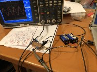
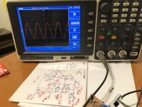
I done some measurements last evening.
I measured the circuit just like it was in the schematic.
.
BUT i switched output transistors with say 10mV offset. Kean was right
Also I spot (and measure) that in the input branch was about 0.38mA not 4mA cca.
About 4mA was total from +V with 1K-Rtrim-1K to -V
With 56ohm R at emitters.
So in the initial original values of the buffer, with Ge devices AC188/AC187 currents are
0.37mA input, 4mA shunt, 8.4mA output.
.
With batteries of +- 8.35V cca
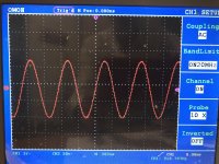
- The buffer holds input signal of 3.3V P-P cca. without clipping. I didnt have more output on the computer...
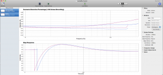
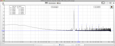
- Distortion is below sensitivity of the measurement equipment and didnt show almost any increase of distortion WITH Ge Buffer.
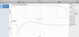
- Transfer is the same as without Buffer.
- But sound is much better WITH the Gee Buffer.
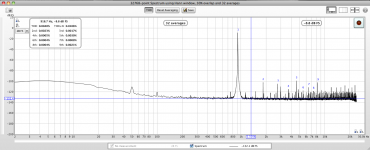
(Some moderate measurements indicate that Distortion at HF region are smaller with buffer with a same transfer and phase shift.)
- Distortion with Ge buffer is a bit smaller against the JFET classic buffer (with same battery supply)
.
[For measurements I use old MBP17 in. Soft for distortion measurements REW, for transfer FuzzMeasurePro, other AcousticToolBox...
MBP17in have 27.3K of input R measured as the Load. Impulse is negative because I dint use compensation. It is tha same with and withput buffer, so buffer does NOT invert phase...]
.
I done some measurements last evening.
I measured the circuit just like it was in the schematic.
.
BUT i switched output transistors with say 10mV offset. Kean was right
Also I spot (and measure) that in the input branch was about 0.38mA not 4mA cca.
About 4mA was total from +V with 1K-Rtrim-1K to -V
With 56ohm R at emitters.
So in the initial original values of the buffer, with Ge devices AC188/AC187 currents are
0.37mA input, 4mA shunt, 8.4mA output.
.
With batteries of +- 8.35V cca
- The buffer holds input signal of 3.3V P-P cca. without clipping. I didnt have more output on the computer...
- Distortion is below sensitivity of the measurement equipment and didnt show almost any increase of distortion WITH Ge Buffer.
- Transfer is the same as without Buffer.
- But sound is much better WITH the Gee Buffer.
(Some moderate measurements indicate that Distortion at HF region are smaller with buffer with a same transfer and phase shift.)
- Distortion with Ge buffer is a bit smaller against the JFET classic buffer (with same battery supply)
.
[For measurements I use old MBP17 in. Soft for distortion measurements REW, for transfer FuzzMeasurePro, other AcousticToolBox...
MBP17in have 27.3K of input R measured as the Load. Impulse is negative because I dint use compensation. It is tha same with and withput buffer, so buffer does NOT invert phase...]
.
Attachments
Last edited:
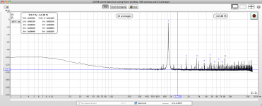
Yes. It is lower with buffer in critical domain for Digital sources... But something that it could not be seen from the measurements - the sound is really strong, with natural echoes coming from low end. NOT from HF end as usual. And without making a focus and emphesizing "end" of musical "event", but start of the event. All instruments and Voices. (Interestingly guitars are neutral...). For my ears, removing crispy ends, and sharp edges with opening space among events. It is not like good tube design does, Ge-s are somehow different? BUT i think that will be good with tube followed?
.
I didnt stand and made other tests:
- moved input branch Ge-s from 0.37ma to about 0.7mA adding parallel to 56ohm 100ohm resistors. (And adjust 1/2+Vb, and offsets)
-with 22ohms parallel to 56ohms 2xR cirrent was 1.04mA.
Everythig else could be adjusted with minimum offset arround 10mV or smaller.
.
I even short-cut resitors and it was without 56ohm resitors about 1.4mA in input branch.
.
So I stay with 1mA with input and measure the device - pretty much the same results. But again I dont know what happening below, and with generating signal with proper analog genarator, maybe some square signals... I will borrow from a friend and make tests later.
.
I didnt spot any change about changing values of "upper" R (56ohms), so I measure and set the same currents to the input transistors. Maybe not the same because of leackege curents from output bases which are higher than the Si BJTs?
.
Anyway somehow the circuit always showed pretty much the same behaviour and sound.
.
.
I didnt stand and made other tests:
- moved input branch Ge-s from 0.37ma to about 0.7mA adding parallel to 56ohm 100ohm resistors. (And adjust 1/2+Vb, and offsets)
-with 22ohms parallel to 56ohms 2xR cirrent was 1.04mA.
Everythig else could be adjusted with minimum offset arround 10mV or smaller.
.
I even short-cut resitors and it was without 56ohm resitors about 1.4mA in input branch.
.
So I stay with 1mA with input and measure the device - pretty much the same results. But again I dont know what happening below, and with generating signal with proper analog genarator, maybe some square signals... I will borrow from a friend and make tests later.
.
I didnt spot any change about changing values of "upper" R (56ohms), so I measure and set the same currents to the input transistors. Maybe not the same because of leackege curents from output bases which are higher than the Si BJTs?
.
Anyway somehow the circuit always showed pretty much the same behaviour and sound.
.
Last edited:
I forgot to say all this i prepared without thermal coupling of pairs. Without coupling, device slowly coming to the point values. I think that with thermal coupling things will be better in that way?
I had some holders, but as ysusal, they was bigger diameter and for other type of Ge devices
.
I will try with thick copper?
I had some holders, but as ysusal, they was bigger diameter and for other type of Ge devices
.
I will try with thick copper?
I spot the same with Ge-s too...
.
I tried yesterday AD161 in the "output". (for now also without thermal coupling.) And it wotking good too.
Also find some mistake and correct it. C in the collector of input transistor is opposite polarity. At this point voltage is negative and about slight more from 1/2 -Vb.
.
After that I add 470uF value of capacitors and also in the power rails. Put the buffer from batteries to +-12V power supply. Every TP was adusted. Absolutly any hum, hiss or anything comimg from the speaker...
And sound was even better. Better body and low mids with these bigger Cs...
.
Tried 32K input resistor (10K+22K series) and offset was adustable to zero. output segment from AD161 vintage Siemens parts, consumed 12mA. (I just need higher input value because of the fiter before buffer, Has to be higher termination impedance to avoid peaks at the cut off F...)
At he input of the buffer I put 4x1uF C.
.
With this bigger value of 4 x C (470uF) I didnt have any clicks or anything with power ON/OFF. So the Ge version coud be used without relay at the output.
.
I will post the measured values of the components and bias points.
All distortion remain the same like it was from the beguining. Nothinf is changed.
.
I didnt solder RC input (270ohm-15pF), beacuse I have already lowpass filter at tinput. Also I prepare but didnt solder 2.2uH FB because I think that Ge-s are much lower Fcutoff than Si-s is it OK?
.
I tried yesterday AD161 in the "output". (for now also without thermal coupling.) And it wotking good too.
Also find some mistake and correct it. C in the collector of input transistor is opposite polarity. At this point voltage is negative and about slight more from 1/2 -Vb.
.
After that I add 470uF value of capacitors and also in the power rails. Put the buffer from batteries to +-12V power supply. Every TP was adusted. Absolutly any hum, hiss or anything comimg from the speaker...
And sound was even better. Better body and low mids with these bigger Cs...
.
Tried 32K input resistor (10K+22K series) and offset was adustable to zero. output segment from AD161 vintage Siemens parts, consumed 12mA. (I just need higher input value because of the fiter before buffer, Has to be higher termination impedance to avoid peaks at the cut off F...)
At he input of the buffer I put 4x1uF C.
.
With this bigger value of 4 x C (470uF) I didnt have any clicks or anything with power ON/OFF. So the Ge version coud be used without relay at the output.
.
I will post the measured values of the components and bias points.
All distortion remain the same like it was from the beguining. Nothinf is changed.
.
I didnt solder RC input (270ohm-15pF), beacuse I have already lowpass filter at tinput. Also I prepare but didnt solder 2.2uH FB because I think that Ge-s are much lower Fcutoff than Si-s is it OK?
Last edited:
pic
C2 should be in opposite polarity, because at the collector we have something about 1/2 -Vb... First I didnt spot this and solder in wrong way, later in proper way connected somehow offset was easy to adjust and it was more stabile? With additionof 470uF to 10uF everything was better.
Conclusion is:
-This buffer can work with AC188 inoput pair
-and AC187 output couple, as with AD161 output. Probably with other Germanium devices but not tested
-Tested with +-9V and +-12V power supply.
-Tested with input signal of 3.4V P-P. probably can accept more p-p...
-No hum or his, no on/off clicks and pops.
-Ditortion is wery low with Ge-s, and lower than source with HF region. Wich is from crucial for digital sources...
-Sound is - just BIG and natural
.
Attachments
Last edited:
I came across your buffer and I like the simplicity of it and the idea behind it. Also the compact size makes it a good candidate for my Soekris DAM1941 build.
I had a question though. Could 2 Kuartlotrons be modified to be used as a balanced to single ended converter after a quad of Kuartlotrons behind the balanced signal of the DAM1941?
I had a question though. Could 2 Kuartlotrons be modified to be used as a balanced to single ended converter after a quad of Kuartlotrons behind the balanced signal of the DAM1941?
- Home
- Source & Line
- Analog Line Level
- The Kuartlotron - keantoken's simple error-correction superbuffer