Hi,
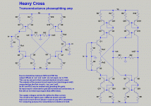
when fiddling and simming around with global-feedback-free transconductance and current conveyor structures, I tried to sketch a circuit that could be used as a SE-to-balanced converter, or as fully differential preamp.
I came up with the circuit to the very left.
When redrawing and tidying up the sketches the circuit to the 2nd left evolved, which is identical apart from the improved current mirrors.
Basically I drew 1 input instead of 2 and Q2 and the parts in its collector branch changed places with the parts from Q1´s emitter branch.
Seeing the sketch to the right I knew I had seen something similar somewhere before.
Anyway, I gave it the name Heavy Cross due to the crosswise interconnection of the current mirrors, and besides for me its the very best song from Gossip.
This circuit simmed very well already, the output offset voltages differed slightly, which is due to the NPN and PNP-branch not beeing true complementary.
The asymmetry also showed in different THD-values, although on a very low niveau.
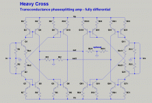
Then I added a second, mostly identical circuit to see if this could symmetrize things and to provide for a second inverting input.
See 2nd attachment.
The only difference beeing interchanged outputs of the two branches.
The 2 output-pairs are connected together, which is possible since we are working in the current domain.
The inv input of the second circuit may then be connected to gnd, or fed with a inverted input signal.
So we can convert SE-to-balanced or work in fully differential mode.
In any case will the output offsets and THD now be equal.
The idle currents are defined mainly by the value of the Res and(!) the supply voltages.
Fortunately this doesn´t spoil the PSRR, so the requirements regarding the power supplies remain feasable.
jauu
Calvin
ps. well I finally remembered ... the Paradise Phono uses a very similar topology
when fiddling and simming around with global-feedback-free transconductance and current conveyor structures, I tried to sketch a circuit that could be used as a SE-to-balanced converter, or as fully differential preamp.
I came up with the circuit to the very left.
When redrawing and tidying up the sketches the circuit to the 2nd left evolved, which is identical apart from the improved current mirrors.
Basically I drew 1 input instead of 2 and Q2 and the parts in its collector branch changed places with the parts from Q1´s emitter branch.
Seeing the sketch to the right I knew I had seen something similar somewhere before.
Anyway, I gave it the name Heavy Cross due to the crosswise interconnection of the current mirrors, and besides for me its the very best song from Gossip.
This circuit simmed very well already, the output offset voltages differed slightly, which is due to the NPN and PNP-branch not beeing true complementary.
The asymmetry also showed in different THD-values, although on a very low niveau.
Then I added a second, mostly identical circuit to see if this could symmetrize things and to provide for a second inverting input.
See 2nd attachment.
The only difference beeing interchanged outputs of the two branches.
The 2 output-pairs are connected together, which is possible since we are working in the current domain.
The inv input of the second circuit may then be connected to gnd, or fed with a inverted input signal.
So we can convert SE-to-balanced or work in fully differential mode.
In any case will the output offsets and THD now be equal.
The idle currents are defined mainly by the value of the Res and(!) the supply voltages.
Fortunately this doesn´t spoil the PSRR, so the requirements regarding the power supplies remain feasable.
jauu
Calvin
ps. well I finally remembered ... the Paradise Phono uses a very similar topology
Attachments
Last edited:
Hi,
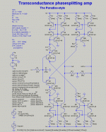
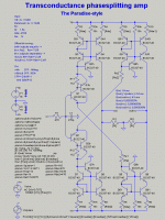
here´s the schematic for a totally paradiseish phase splitter.
I must stress that at the time the schematic is just brainworks and Sims.
It still needs real world testing.
Anyway, comparing it to the schematic of the Paradise Rev.3 and You´ll notice the similarities.
Paradise | HeavyCross
Input stage NPN:
Q1,30,31,32 | Q1,1b
Input stage PNP:
Q2,25,26,29 | Q2,2b
NPN Emitter Current Mirror:
Q4,5,13,14 | Q5,6,51,61,5h
PNP Emitter Current mirror:
Q11,12,15,16 | Q9,10,91,101,9h
NPN Collector Current Mirror:
Q3,10,17,18,22 | Q3,4,31,41,3h
PNP Collector Current Mirror:
Q6,7,8,9,24 | Q7,8,71,81,7h
NPN Emitter Resistors:
R2,21,22,23 | Re1
PNP Emitter Resistors:
R24,25,26,28 | Re2
Differences mainly occur in the Collector branches of the Current mirrors and the CM-topology.
The Paradise has a CCS loading the Emitter-side-CMs (Q49,50,51,52, R5,30,36).
This CCS defines the idle currents of the whole circuit.
The CMs beeing of cascoded type.
The Collector-side-CMs are loaded by the RIAA network.
The CMs here beeing of improved Wilson w. helper type.
The HeavyCross´s CMs are all of the improved Wilson w. helper type to achieve maximum symmetry.
The loads are the identical Ri and Ri2 for both branches.
The idle currents are defined by RE1 and Re2 and the level of the supply voltages.
Due to differences between the NPN and PNP transistors the Outputs will settle at different Offsets and exhibit slightly different THD.
To keep Offsets small NPNs and PNPs should be matched as should be the input Pairs Q1,1b,2,2b.
There are two ways to cancel the Offsets.
1) Trimming Re2.
As the Offsets are of similar level but opposite polarity it might suffice to trim only Re2. The Offsets should become 0V if the currents through Re1 and Re2 equal in value.
2) Trimming R8 and R10.
This trims the idle currents of the PNP-CMs.
The Paradise Offset is trimmed in that the idle currents through the Emitter-CMs of NPN and PNP branch are varied and as such they also affect the idle currents through the Collector-CMs, hence the output offset.
A minor difference occurs in the Input stage.
The paradise uses multiple paralleled transistors to achieve the required low-noise characteristic.
The HeavyCross makes use of either just a single complementary pair (Q1,Q2) or optionally of a Complementary-Feedback-Pair (CFP, Q1,1b,R11 and Q2,2b,R12).
With the former the input impedance settles at app. 300k.
If that proves to be a bit low --remember that the Zin directly affects the RIAA equalizer and that therefore the 100k input resistor of the Calvin Buffer had to be omitted with-- the CFP may be used raising the Zin to roundabout 14Megs.
So there are certain differences due to the different application, but I think the basic topological similarities are noticeable.
Interestingly didn´t the more elaborated CMs improve the THD-figures against the basic two transistor CM.
So if anybody starts testing, he might want to start start with the simple leftmost schematic of #1 and parts and values from #3.
It it were to be used with the Paradise the HeavyCross would be inserted at the output of the RIAA-Equalizer Network.
Its two outputs were connected to two Buffers, say the Calvins.
The output of the Calvin-Buffer connected to the V(out) output of the HeavyCross would be connected to the DC-servo input.
Trimming the HeavyCross´s output Offsets should be done either before putting it into the Paradise or in that the input of the HeavyCross is grounded and the outputs trimmed to 0V.
jauu
Calvin
ps. Joachim I forgot to ask for Your permission or approvement of this add-on.
Is it ok, or shall I shutup and p***off?
Attachments
Last edited:
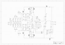
Hi,
You´re right if its used standalone.
Then I´d add a bandwidth-limiting filter with DC-bias path.
But for the Parasise its correct as the preceeding RIAA network serves as DC-path and a additional R would alter the RIAA-response.
R1,C1 serve her just as soft-filter against HF entering the circuit.
So here´s something for show and tell
jauu
Calvin
Attachments
Last edited:
Hi,
doesn´t seem so.
Though the working principle is very simple, the whole circuit probabely looks too complex to be trusted
Also, as is, it´d be just at the beginning of its development.
Subassemblies like a dc-servo may be added as well as variants with current inputs to be used as I/V converter, or MC-prepre.
jauu
Calvin
- Status
- This old topic is closed. If you want to reopen this topic, contact a moderator using the "Report Post" button.
- Home
- Source & Line
- Analog Line Level
- The Heavy Cross - ideas about a transconductance phase-splitting amp