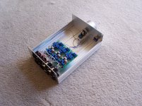
A home build balanced LDR attenuator, it had wide control range,good phase balance and channel balance. The most good feature is it don't required four or five current point match LDR, It only need two current point selected LDR, 5ma and 30ua.
Almost all LDR can be used. The attenuator used pots to set each LDR at 50 ohm, 400 ohm, 1.5 Kohm, 5 Kohm and above.
This attenuator had two independent balanced input and two parallel output.
The design is base on balanced bridge circuit.
Other feature is the series and shunt resistance can adjusted from few K ohm to few hundred K ohm by the user.
Attachments
The cold and hot pair of LDR resistance are very closed. It works like this:
first adjusted the cold pair or hot pair of LDR to the same resistance at four point, I select 50-100ohm, 400-500ohm,1.5-2kohm and 50-100Kohm as the four calibrate point for series LDR.
Then adjusted the L/R channel of hot and cold pair to the same resistance at four point by the pots.
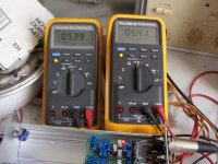
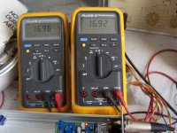
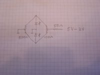
the design works like this, with a 5v DC supply if a pair of LDR led,each series with a 2v LED and parallel by a 100 ohm pot, we can adjusted the pot until both LDR to the same valve, about 40 to 70 ohm,this is high current path.
Then if the DC supply change to 3v, no current will flow to the LDR LED by the high current path but can flow to low current path which series a resistor and a pot work as a voltage divider.
Instead of variable the resistance or current like other design, I am variable
the DC supply voltage.
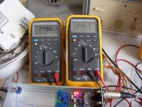
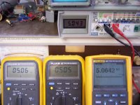
I had attach few pictures for one hot pair of LDR for L channel with two meter and a diagram.
first adjusted the cold pair or hot pair of LDR to the same resistance at four point, I select 50-100ohm, 400-500ohm,1.5-2kohm and 50-100Kohm as the four calibrate point for series LDR.
Then adjusted the L/R channel of hot and cold pair to the same resistance at four point by the pots.
the design works like this, with a 5v DC supply if a pair of LDR led,each series with a 2v LED and parallel by a 100 ohm pot, we can adjusted the pot until both LDR to the same valve, about 40 to 70 ohm,this is high current path.
Then if the DC supply change to 3v, no current will flow to the LDR LED by the high current path but can flow to low current path which series a resistor and a pot work as a voltage divider.
Instead of variable the resistance or current like other design, I am variable
the DC supply voltage.
I had attach few pictures for one hot pair of LDR for L channel with two meter and a diagram.
Attachments
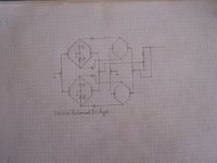
I rewrite a one balanced bridge circuit for easy understand.
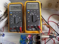
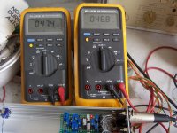
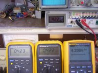
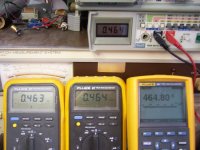
Here how it works: supply around 4V and adjusted the 100R trim pot until
both LDR resistance equal at about 70R to 100R.
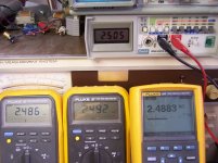
Reduced the supply V to around 2.5V and adjusted the 500R trim pot until
both LDR resistance equal at about 400R to 500R. It need to repeat few times at 4V/2.5V until both high end and low end balanced.
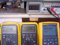
At this time if you change the supply V from 5V to 2.5V, both LDR resistance
value are very closed from around 50R to 400R.
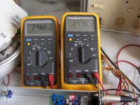
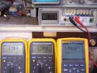
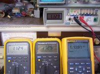
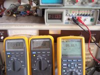
I had post some pictures on four shunt LDR, I had set the impedance to 5KR.
The four LDR resistance match good from 40R to 5KR for un-match LDR.
Here how it works: supply around 4V and adjusted the 100R trim pot until
both LDR resistance equal at about 70R to 100R.
Reduced the supply V to around 2.5V and adjusted the 500R trim pot until
both LDR resistance equal at about 400R to 500R. It need to repeat few times at 4V/2.5V until both high end and low end balanced.
At this time if you change the supply V from 5V to 2.5V, both LDR resistance
value are very closed from around 50R to 400R.
I had post some pictures on four shunt LDR, I had set the impedance to 5KR.
The four LDR resistance match good from 40R to 5KR for un-match LDR.
Attachments
-
 100_2597.JPG939.3 KB · Views: 40
 -
 100_2596.jpg490.5 KB · Views: 28
 -
 100_2595.JPG847.7 KB · Views: 35
 -
 100_2594.jpg529.9 KB · Views: 35
 -
 100_2593.JPG836.8 KB · Views: 40
 -
 100_2592.JPG850.4 KB · Views: 52
 -
 100_2607.JPG935.3 KB · Views: 130
 -
 100_2608.JPG528.1 KB · Views: 127
 -
 100_2598.JPG893 KB · Views: 42
- Status
- This old topic is closed. If you want to reopen this topic, contact a moderator using the "Report Post" button.